
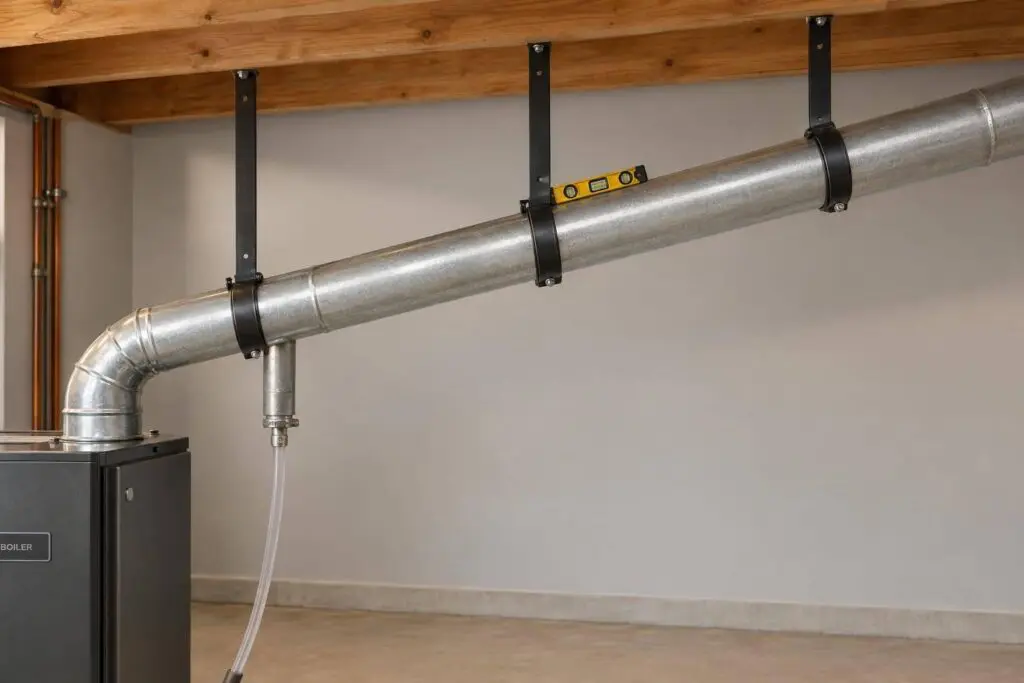
I check boiler vent slope and supports together: the right pitch won’t hold if the pipe sags. Natural-draft connectors generally need an upward slope of at least 1/4 inch per foot – about 2.1% – toward the chimney or vent. For condensing and mechanical-draft systems, I check the adopted code and exact boiler and vent instructions before choosing the slope direction or support spacing.
Here’s my short checklist:
- Confirm the system. Sealed combustion does not always mean condensing. Check approved materials, joints, clearances, and termination requirements.
- Measure after final fastening. Check each horizontal segment and between supports – not just the endpoints – for sag or reverse pitch.
- Trace the drainage path. Verify traps, drains, freeze protection, and any required neutralizer separately from vent slope.
- Document and test. Record measurements, resolve code or manual conflicts with the manufacturer and local authority, and have qualified personnel complete the required tests.
<u>Correct slope is only part of a safe installation.</u> If a CO alarm sounds or you suspect flue gas indoors, leave the building and call emergency services or the gas utility from a safe location.
B vent installations, b vent clearance, b vent support
sbb-itb-b5c10b1
1. Code Requirements for Slope
The 2024 IFGC and NFPA 54 require natural-draft vent connectors to slope upward at least 1/4 inch per foot, with no dips or sags. Follow the locally adopted edition and amendments. Proper support must keep the connector from sagging so it maintains that slope.
Pitch is just one compliance check. Connector rise, horizontal-length limits, and vent sizing are separate requirements.
The IFGC allows an exception for connectors attached to mechanical-draft systems when installed according to the appliance and draft-system manufacturers’ instructions. For these systems, the manufacturers’ instructions govern pitch and support layout.
For condensing boilers, follow the manufacturer’s requirements for condensate collection, drainage, and disposal. Correct pitch alone isn’t enough if the drain or trap is missing or blocked. When code and instructions differ, the installation must follow the adopted code path before any fastening is finalized.
If an instruction conflicts with an applicable code requirement, stop before installation. Verify the adopted code, the appliance instructions, and the direction of the authority having jurisdiction (AHJ).
2. Slope Checks in the Field
Mark the required slope direction at both ends of each horizontal segment before measuring. A higher endpoint alone doesn’t confirm correct pitch.
Then check the installed run at multiple points. Use a level or digital inclinometer on each straight run, and a laser level or straightedge on longer runs. Measure before and after elbows, couplings, reducers, and adapters. Check between hangers, too – sag can hide a low spot. Look for visible sag, reverse-pitch readings, joint staining, or water marks. Recheck the fully assembled vent after final fastening.
Once you’ve confirmed the slope, trace the condensate path to the approved drain point. Check that the slope and supports allow continuous drainage. Make sure the trap, drain tee, and tubing are installed as specified, with no blockages or reverse pitch. Check vent slope and condensate-drain slope separately. Also check whether the discharge location could allow condensate to freeze, cause corrosion, or create a slip hazard.
3. Manufacturer Slope and Drainage Instructions
Follow the installation instructions for the exact boiler model and listed vent system, including the termination layout. If the manuals conflict, get written direction from the manufacturer or AHJ before proceeding.
When code allows an equipment-based exception, those model-specific instructions govern the field layout. Check the exhaust and combustion-air intake requirements separately. They may call for different slope directions and pitches.
Some condensing-boiler instructions require a continuous pitch toward the boiler. Other vent systems slope toward the termination and may require drain tees or other collection points. Neither direction applies to every system.
Confirm where the condensate must go: the appliance trap, an approved drain tee, a common vent drain point, or another manufacturer-specified location. Then check the discharge point and whether the instructions or local plumbing code require a neutralizer or pump. A nearby floor drain isn’t automatically approved.
The hanger layout and joint supports must maintain the required pitch under load, with no sag.
Vent Support and Joint Stability
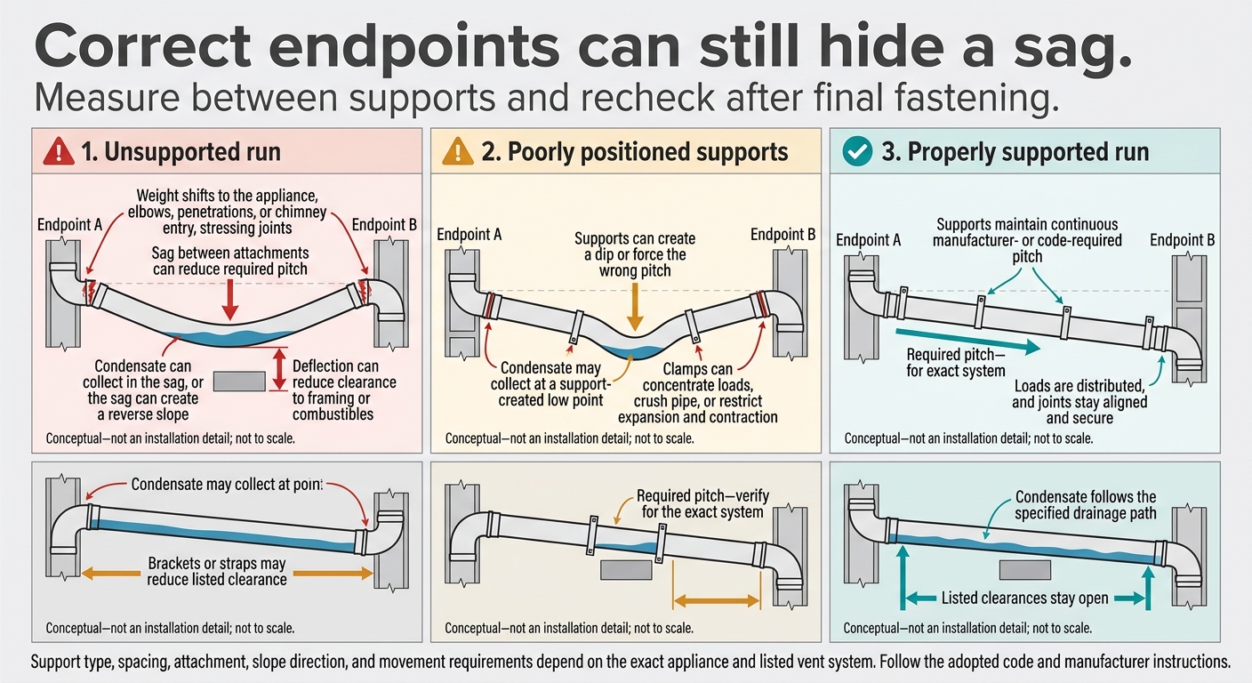
Boiler Vent Supports: How Sag Changes Slope
Once pitch is set, supports must keep it in place. Code requires support that maintains pitch, secures joints, and preserves clearances. In the field, that means placing supports so pitch stays unchanged after fastening, the boiler outlet carries no vent weight, and elbows, offsets, penetrations, and terminations stay stable. Manufacturer instructions specify support type, spacing, attachment, slope direction, and movement requirements. Fewer elbows do not mean fewer supports, and no single hanger spacing works for every vent.
Three common field conditions show how support affects the installation.
| Installation condition | Slope retention | Joint stress | Condensate behavior | Clearances |
|---|---|---|---|---|
| Unsupported run | Sag between attachments can reduce required pitch | Weight shifts to the appliance, elbows, penetrations, or chimney entry, stressing joints | Condensate can collect in the sag, or the sag can create a reverse slope | Deflection can reduce clearance to framing or combustibles |
| Poorly positioned supports | Supports can create a dip or force the wrong pitch | Clamps can concentrate loads, crush pipe, or restrict expansion and contraction | Condensate may collect at a support-created low point | Brackets or straps may reduce listed clearance |
| Properly supported run | Supports maintain continuous manufacturer- or code-required pitch | Loads are distributed, and joints stay aligned and secure | Condensate follows the specified drainage path | Listed clearances stay open |
Supporting Natural-Draft Connectors
Use approved hangers, straps, brackets, and fasteners matched to the connector material. They must maintain upward pitch and clearances while keeping the vent load off the boiler outlet. Add support near elbows and offsets, where vertical loads transfer into horizontal runs.
At chimney entries, keep the connector engaged without reducing the flue opening. Do not rely on the chimney entry or wall thimble to carry the run. At penetrations and terminations, use the specified support arrangement instead of letting the pipe rest against the opening. Check that the connector’s pitch remains unchanged after final fastening.
Supporting Sealed-Combustion and Condensing Vents
Identify the appliance category and vent material before choosing supports. Follow the required spacing, attachment details, and joint-securing method. Check elbows, offsets, penetrations, and terminations for added load points.
Correct endpoint elevations can still hide a sag that traps condensate. Supports must maintain alignment without crushing the pipe, stressing seals, or restricting expansion and contraction. Use fixed supports or supports that allow movement, as specified – not tight clamps throughout the run. After the vent reaches operating temperature, inspect for shifted joints, new low spots, and contact with surrounding materials. If you notice leaks or structural issues during this inspection, immediate boiler repair is necessary to prevent hazardous conditions.
Include these support checks in the final compliance review as part of a professional boiler installation.
Code Compliance and Installation Checks
Once slope and support are set, check the adopted code, listed system, and installation manual before final acceptance.
Confirm Adopted Codes and Applicable Manuals
Confirm the jurisdiction, adopted code edition, local amendments, permit conditions, and exact manual revision. Identify the boiler model, listing, vent-system category, and approved vent materials. Follow the adopted code – not the latest national edition or common site practice.
Compare code requirements, field measurements, and manufacturer instructions. If the code, listing, and manual appear to conflict, document the issue. Get clarification from the manufacturer and authority having jurisdiction (AHJ) before installation proceeds.
| Verification point | Code requirement to confirm | Field check | Manufacturer instruction to confirm |
|---|---|---|---|
| Materials | Permitted materials, ratings, and listing | Match pipe, fittings, adapters, and seals | Approved components, diameter, and joining products |
| Support spacing | Support and restraint requirements | Measure spans and verify structural attachment | Maximum spacing, hanger type, and added supports |
| Pitch | Applicable slope rule and exceptions | Measure segments and intermediate elevations | Required direction and exact pitch |
| Joints | Joining and sealing requirements | Check engagement, locking, seals, and penetrations made without approval | Permitted fasteners, gaskets, cement, and sealants |
| Clearances | Code and listed-system clearances | Measure at combustibles, penetrations, openings, and terminals | Thimbles, firestops, shields, and reduced-clearance options |
| Condensate traps and drains | Collection, disposal, freeze protection, and backflow requirements | Check the trap, required priming, routing, and access | Trap arrangement, drain size, slope, venting, neutralizer, freeze protection, and pump limits |
| Neutralizer | Whether treatment is required before discharge | Check flow direction, cartridge, bypass prevention, connection, and access | Approved type, replacement interval, pH, upstream condensate-trap requirements, and restrictions on flue gas entering the device. |
| Termination support | Wall, roof, or vertical support requirements | Check brackets, penetration seals, termination direction, and wind or impact resistance | Terminal clearances, direction, hardware, and maximum unsupported length |
Use these documents to guide the field checks below, then measure the installed run to confirm it meets their requirements.
Check Pitch After Final Fastening
Measure every completed horizontal segment after final fastening. Use a level, laser, or calibrated digital inclinometer. Record each segment’s length and measured rise or fall. Check the center of every span and both sides of elbows: the endpoints may look correct even when the pipe sags between supports.
1/4 inch per foot equals about 2.1% slope; follow the manual for condensing vents.
| Field practice | Potential problem | Verification method |
|---|---|---|
| Supporting only the ends | Mid-span sag, retained condensate, and joint stress | Measure each span and compare supports with the code and manual |
| Assuming support spacing | Spans may exceed listed limits | Compare measured spacing with the manufacturer’s schedule |
| Attaching to unrelated piping or ductwork | Inadequate strength, transmitted movement, or clearance violations | Verify structural attachment, approved hardware, and load capacity |
| Supporting elbows but overlooking transitions or joints | Loads can separate joints or rotate fittings | Check tees, adapters, penetrations, and terminations for required restraint |
| Checking only before fastening | Tightening can change pitch or alignment | Recheck after all attachments are secured |
Record Final Installation Checks
Record the code edition, amendments, manual revision, appliance data, approved materials, support locations, measurements, clearances, and condensate routing. Include pitch readings so the record shows that the vent holds its required slope. Document joint checks and neutralizer details where applicable. Before closure, photograph concealed supports, penetrations, traps, and termination connections.
Have qualified personnel perform the required draft, spillage, combustion, pressure, leak, and vent integrity tests according to the code, listing, and manual. Record instrument readings, test conditions, corrective actions, retest results, and who performed the work. Resolve outstanding discrepancies before concealing or accepting the installation.
Conclusion: Confirm Slope, Support, and Compliance
Before closing out the installation, confirm that the adopted code, appliance manual, and measured performance agree. Use these requirements and final field checks to verify slope, support, and drainage.
Slope direction and support spacing depend on the system. Follow the adopted code and appliance manual together, and make sure supports maintain the required pitch without straining joints. Document the final slope, support locations, and any corrective work before closing out the job.
If the final inspection reveals a problem, stop the job and investigate before startup. Have a qualified technician inspect any sagging, corrosion, condensate leaks, loose joints, or backdrafting.
Suspected flue-gas exposure calls for immediate action. Leave the building if a CO alarm sounds, occupants have possible CO symptoms, or you suspect flue gas indoors. Call emergency services or the gas utility from a safe location. Do not re-enter until authorities or qualified personnel say it is safe, and do not operate the boiler again until it has been evaluated.
FAQs
How do I calculate the required rise for my vent?
As a general guide, slope the vent 1/4 inch per foot back toward the boiler. This lets condensate drain into the boiler’s internal trap instead of pooling in the pipe.
Follow your boiler manufacturer’s instructions and local code, since requirements vary. Support the pipe with rigid hangers or straps every 4 to 6 feet to prevent sagging or reverse pitch, which can trap water and cause corrosion.
Can adding supports fix a sagging boiler vent?
Yes. Adding supports helps remove sags and restore the required slope – often 1/4 inch per foot – so acidic condensate drains back to the boiler or an approved disposal point rather than pooling.
Rigid hangers or straps secured to framing every 4 to 6 feet help hold that slope and keep the vent gas-tight and liquid-tight, preventing corrosion and performance problems.
Does replacing my boiler require updating its venting?
Replacing your boiler almost always requires venting updates. Each model has its own requirements for vent material, diameter, length, and slope.
High-efficiency condensing boilers need gas-tight, liquid-tight venting to handle acidic condensate. If you’re using an old masonry chimney, it needs a specialized liner to protect it from moisture damage caused by cooler exhaust.
Every installation must be checked against the manufacturer’s instructions and local code to confirm it’s safe and meets those requirements.