
I calibrate fans and outdoor air first, then coils and ducts – and check the finished model against data I didn’t use for tuning. Matching the utility bill alone isn’t enough: errors in fan, heating, and cooling energy can cancel each other out.
For a Chicagoland building, I use this sequence:
- Set the boundary: Map the air path, keep central-plant equipment separate, and Check records and sensor data as part of HVAC services across winter, summer, and mild weather.
- Match measured behavior: Check fan kW, airflow in cfm, ventilation, economizer controls, coil output, and duct losses.
- Test each change: Adjust one input group at a time, track the results, and check zone temperature, humidity, and peak demand.
- Validate and hand off: Test against separate data, document uncertainty, and assign field-check responsibilities.
For monthly energy checks, I use the cited ASHRAE Guideline 14 benchmarks: NMBE within ±5% and CVRMSE ≤15%, plus project limits for airflow and comfort. My rule is simple: <u>don’t fix one mismatch by hiding another</u>. The handoff should explain what changed, why it changed, and what still needs checking – not promise future utility costs.
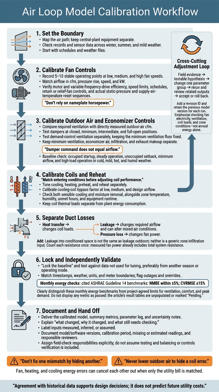
Air Loop Model Calibration Workflow
Calibrate Fan Controls and Outdoor Air
Match Fan Power and Reset Controls
Record 5–10 stable operating points at low, medium, and high fan speeds. Match measured airflow in cfm, pressure rise, speed, and kW. Don’t rely on nameplate horsepower. Verify motor and variable-frequency-drive efficiency, speed limits, schedules, and return or relief-fan controls. A motor in the airstream adds heat, increasing supply-air temperature and cooling load.
Model the actual static-pressure and supply-air-temperature reset sequences rather than fixed design setpoints. Check whether an open VAV box, poor balancing, or a failed sensor is keeping duct pressure too high.
Warmer supply air may reduce reheat, but it can also require more airflow. Excess pressure increases fan electricity use, while incorrect minimum speeds skew part-load energy and ventilation estimates. Check terminal airflow alongside total supply airflow. This fan baseline helps separate ventilation error from total supply-airflow error.
Check Outdoor-Air Rates and Economizer Controls
Once fan behavior is corrected, separate outdoor-air error from supply-air error. Calculate required ventilation using occupancy, floor area, air distribution, and system-efficiency inputs. For ASHRAE 62.1 calculations, breathing-zone airflow is V<sub>bz</sub> = R<sub>p</sub>P<sub>z</sub> + R<sub>a</sub>A<sub>z</sub>, before zone and system adjustments.
Compare that requirement with directly measured outdoor-air cfm. Damper command does not equal airflow. Use indirect airflow estimates only when measurements are reliable, simultaneous, and taken under stable conditions. Treat CO2 trends as supporting evidence – not direct airflow data.
Test dampers at closed, minimum, intermediate, and full-open positions. Check leakage, actuator travel, mixed-air sensors, economizer temperature and enthalpy limits, and the relief-air sequence. Test demand-control ventilation (DCV) separately, keeping the minimum ventilation floor fixed.
Keep minimum ventilation, economizer air, infiltration, and exhaust makeup separate in the model. Excess outdoor air increases conditioning loads. Too little outdoor air can make energy results look favorable while understating ventilation needs. Carry these settings into seasonal and occupancy checks.
Test Seasonal and Occupancy Modes
Check occupied startup, steady operation, unoccupied setback, minimum airflow, and high-load operation in cold, mild, hot, and humid weather. Compare fan kW, outdoor-air cfm, outdoor-air fraction, mixed-air temperature, supply-air temperature, damper position, and coil-valve response.
Cold-weather checks identify leakage errors that distort heating loads. Mild-weather checks identify economizer-control errors that understate free cooling. Hot, humid-weather checks identify incorrect economizer lockouts that distort dehumidification loads. After-hours trends identify unwanted fan operation or outdoor-air admission.
Use these results as the baseline for coil calibration.
sbb-itb-b5c10b1
Fundamentals of Test & Balance for Engineers, Cx & Energy Providers
Calibrate Coils and Duct Losses
Once fan and outdoor-air behavior are calibrated, turn to coil performance and duct losses.
Match Heating, Cooling, and Reheat Performance
Check the model’s coil type, face area, row count, rated capacity, and flow limits against inspection records. For matching times, compare entering- and leaving-air temperature and humidity, airflow, valve position, and entering-water, leaving-water, or refrigerant conditions.
Match entering conditions before adjusting coil performance. Then tune coil effectiveness, bypass factor, performance curves, and part-load response separately for cooling, heating, preheat, and reheat. Cooling-coil bypass factor changes with airflow, so calibrate at low, medium, and design airflow – not just peak load.
Check both sensible cooling and moisture removal. Matching temperature alone doesn’t mean the coil is calibrated if leaving-air humidity is wrong. If a fully open valve produces too little output, check for flow restrictions, fouling, incorrect plant temperatures, and capacity limits. If the valve command doesn’t match, check controls first. Keep preheat freeze-protection logic and terminal-reheat schedules separate from primary heating.
Assess Coil Effects on Energy and Comfort
Connect coil output to zone temperature, humidity, unmet hours, and equipment runtime. Capacity errors distort sizing; controls determine energy use. When cooling and reheat run together, check the cooling-coil leaving-air setpoint, minimum terminal airflow, zone setpoints, and reheat-valve response as a group. Keep reheat in the model when humidity or ventilation control requires it.
Report coil thermal loads separately from energy use so coil demand isn’t confused with plant consumption. Check water-flow limits and water-side pressure drop for their effects on pumps, airside coil pressure drop for its effects on fans, and plant temperatures and efficiency for their effects on chillers or boilers. These checks help prevent coil adjustments from hiding errors in modeled system energy use.
Separate Duct Heat Transfer, Leakage, and Pressure Loss
Once coil output matches measured performance, isolate distribution losses that still affect energy use and comfort. Map supply and return runs by location, insulation, surrounding-air temperature, airflow, and static pressure. Temperature changes along a run help identify heat transfer. Airflow imbalances and leakage tests help identify reduced delivered airflow.
Leakage into conditioned space is not the same as leakage outdoors. Neither belongs in the model as a generic zone-infiltration input. Heat transfer changes coil loads. Leakage changes required airflow and can alter mixed-air conditions. Pressure loss changes fan power.
Count each resistance once: measured fan power already includes total system resistance. Record each loss separately before testing its effect on comfort and required equipment capacity.
Carry these coil and duct settings into the validation step.
Validate Results and Record Changes
Once fan, outdoor-air, coil, and duct settings are tuned, lock the baseline and validate it against separate data.
Adjust One Parameter Group at a Time
Assign each run a revision ID and change only one parameter group at a time. Start with schedules and weather files. Then check airflow and fan controls, outdoor-air rates and economizer settings, coils and reheat, and ducts and leakage.
Tie every change to field evidence, a testable hypothesis, and a verification result. Keep inputs within physically plausible limits backed by drawings, controls data, commissioning records, or field measurements. Never lower outdoor air to hide a coil error.
After each change, rerun the model and review related outputs before accepting the adjustment. Check fan electricity, supply-air temperature, coil loads, ventilation, and zone conditions during occupied and unoccupied periods, seasonal extremes, economizer operation, minimum ventilation, and part-load operation. Keep the previous version so you can roll back. Annual energy alone is not enough to accept a run.
Validate Against Separate Operating Data
Validate with data that wasn’t used for tuning, preferably from another season or operating mode. This keeps the check independent. Match timestamps, weather, units, and meter boundaries, and flag outages and overrides.
Report normalized mean bias error (NMBE) to assess systematic error and CVRMSE to assess error spread. Use the project’s agreed acceptance limits established earlier. Set separate limits for ventilation, comfort, and peak demand. Compare coil thermal loads separately from purchased energy, and keep unrelated utility loads separate.
Use this record structure:
| Parameter group | Metric | Measured | Baseline | Calibrated | Pass/fail |
|---|---|---|---|---|---|
| Fan controls | Fan electricity; peak demand, kW | – | – | – | Pending |
| Outdoor air | Outdoor-air flow, cfm | – | – | – | Pending |
| Coils/reheat | Coil loads, Btu; zone temperature, °F; unmet hours | – | – | – | Pending |
| Ducts | Delivered airflow, cfm; pressure loss, in. w.c. | – | – | – | Pending |
Create a Calibration Matrix and Parameter Log
Document every accepted change in a traceable log, including the evidence behind each adjustment. Record validation results only after testing.
In the linked parameter log, include baseline and calibrated values, units, model location, source, date, analyst, reviewer, physical bounds, annual energy sensitivity, and uncertainty. Label each input as measured, inferred, or assumed.
If the data can’t separate fan efficiency from duct leakage, keep alternatives within supported bounds. Identify the field measurement needed to tell them apart.
| Parameter group | Field evidence | Model input | Diagnostic trend | Model impact | Adjustment | Validation result |
|---|---|---|---|---|---|---|
| Schedules/weather | BAS schedules; weather records | Runtime; weather file | Load timing | Annual use and peaks | Correct documented mismatch | Pending |
| Fan controls | Fan meter; speed; pressure | Fan curve; reset logic | Power versus airflow | Fan electricity | Revise supported inputs | Pending |
| Outdoor air | TAB report; airflow trends | Minimum cfm; economizer limits | Flow versus operating mode | Conditioning energy | Match verified sequence | Pending |
| Coils/reheat | Temperatures; flow; valve trends | Capacity; control limits | Load and discharge temperature | Heating/cooling demand | Correct supported mismatch | Pending |
| Ducts | Leakage tests; pressure readings | Leakage; resistance | Delivered airflow and pressure | Fan and coil energy | Revise losses separately | Pending |
Conclusion: Deliver the Calibrated Design Model
Release the model only when as-built records and measured data support its inputs. Include the calibrated model, summary metrics, and uncertainty notes in the handoff. Agreement with historical data supports design decisions; it does not predict future utility costs.
Hand Over the Model and Energy Summary
Once validation is complete, deliver the final model file along with calibrated schedules, control sequences, coil inputs, outdoor-air and economizer settings, duct-loss assumptions, zone connections, weather-file data, and the parameter log. Document the model and software versions, calibration period, missing or estimated readings, and responsible reviewers.
Use the table below to record final results and acceptance status. Define the measurement boundaries and reporting periods. Use the project interval for energy checks and representative operating periods for airflow and temperature checks. Report percentage differences for energy and airflow, but absolute differences for temperature and humidity.
| Metric | Measured result/source | Calibrated-model result | Reported difference | Acceptance criterion/status |
|---|---|---|---|---|
| Electricity use, kWh | Utility meter or submeter | Same boundary and interval | kWh and % | Owner-approved limit; pass/fail |
| Heating energy, therms or kBtu | Fuel meter or thermal meter | Same boundary, interval, and units | Units and % | Owner-approved limit; pass/fail |
| Supply airflow, cfm | Field measurements or verified trends | Corresponding air-loop flow | cfm and % | Owner-approved limit; pass/fail |
| Outdoor-airflow rate, cfm | Field measurements or verified trends | Corresponding air-loop flow | cfm and % | Owner-approved limit; pass/fail |
| Supply-air temperature, °F | Verified sensor trends | Corresponding air temperature | °F | Owner-approved limit; pass/fail |
| Mixed-air temperature, °F | Verified sensor trends | Corresponding air temperature | °F | Owner-approved limit; pass/fail |
| Zone temperature, °F; humidity, % RH | Representative zone measurements | Matching zone conditions | °F; percentage points | Owner-approved limit; pass/fail |
Report costs in U.S. dollars using documented local utility tariffs. Record the utility, rate schedule, effective date, billing period, and service class. Separate energy, demand, fixed charges, taxes, riders, and other applicable fees, and state whether costs are nominal or escalated.
Include ranges for important unresolved inputs. Identify which design conclusions remain reliable across those ranges.
Coordinate Field Checks in Chicagoland
Make field verification responsibilities part of the handoff for Chicagoland projects. Eco Temp HVAC can coordinate maintenance records, equipment checks, seasonal inspections, and performance verification.
Before work starts, confirm instrumentation, measurement methods, trend access, scope, and written deliverables. Do not assume testing and balancing or controls verification is included. Assign those responsibilities explicitly.
FAQs
Can I calibrate an air loop with limited sensor data?
Yes, but you’ll need a reliable baseline and a clear verification process. Audit control sequences, schedules, and setpoints. Then use 12 months of utility history, occupancy patterns, and local weather data to build a weather-normalized baseline.
Check airflow, static pressure, and temperatures using independent, calibrated instruments. Without full telemetry, you’ll need to test occupied and unoccupied modes, economizer operation, and demand-controlled ventilation responses to confirm the system works as intended.
How can I distinguish coil errors from duct losses?
Compare measured airflow and pressure with the expected performance of the equipment and coil. Coil problems typically cause temperature issues or reduced airflow tied to refrigerant problems or restrictions near the unit. Duct losses create a gap between expected and delivered performance through leakage, heat loss, or static pressure losses.
Check fan controls, airflow, duct static pressure, and air distribution to tell whether the problem comes from restricted duct paths or the coil.
When should I recalibrate my air loop model?
Recalibrate when installed equipment, control sequences, or operating settings don’t match the model’s assumptions. High energy bills without a clear equipment fault are another reason to recalibrate. They may point to sensor drift, scheduling errors, or heating and cooling running at the same time.
Update your baseline and recalibrate after major building changes, such as energy-saving upgrades. Do the same when commissioning shows that measured airflow or temperature differences don’t match the design intent.