
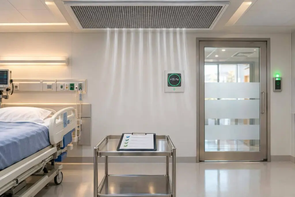
I check the room – not just the HEPA filter. A filter rated to remove 99.97% of particles at 0.3 µm does not prove that your hospital room meets its airflow, pressure, or alarm requirements.
In this guide, I explain how to:
- Set room-specific limits using adopted standards, Illinois requirements, and approved plans.
- Check filter installation, measure airflow and pressure, and test for HEPA leaks.
- Test alarms, controls, power loss, and recovery.
- Correct failed results, retest, and document approval before clinical use.
My starting point: <u>confirm the room’s intended use</u>. That determines what you test and what counts as a pass. Keep outdoor airflow, total air changes, and HEPA recirculation separate – and set future testing dates based on requirements, room risk, and system changes.
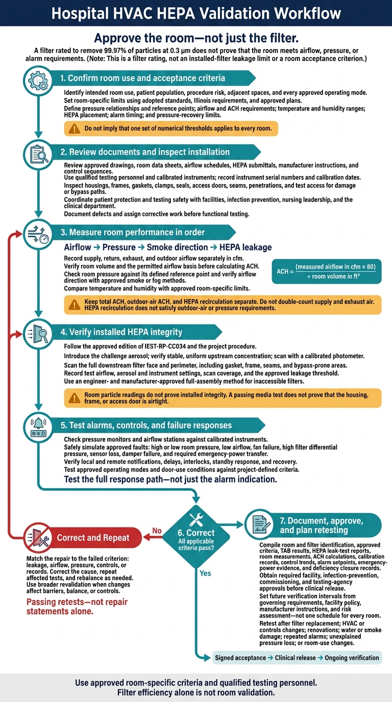
Hospital HVAC HEPA Validation Workflow
Room Types and Acceptance Criteria
Room Types, Pressure, ACH, and HEPA Placement
Start with the room’s function, patient population, procedure risk, and adjacent spaces. Then use the matrix below to select room-specific acceptance criteria for pressure, airflow, and HEPA placement.
| Room type | Pressure relationship | Minimum ACH or airflow basis | HEPA location | Exhaust arrangement | Core acceptance tests |
|---|---|---|---|---|---|
| Airborne infection isolation room (AIIR) | Negative to the corridor and adjacent spaces | At least 6 ACH in existing rooms; at least 12 ACH in new or renovated rooms | Supply HEPA where specified; exhaust/return HEPA before recirculation | Direct exhaust outdoors where feasible; otherwise, HEPA-filter before recirculation | ACH, room pressure, smoke direction, exhaust flow, HEPA integrity, alarms |
| Protective environment (PE) | Positive to the corridor and less-clean spaces | At least 12 ACH | Supply-side HEPA, terminal or central, as designed | Maintain positive pressure and prevent infiltration | ACH, pressure, airflow direction, HEPA integrity, temperature and humidity, alarms |
| Combination PE/AIIR | Negative for isolation; positive only when specifically engineered and permitted | Apply the criteria for the active mode | Dedicated, mode-compatible supply and/or exhaust HEPA | Anteroom with independent contaminated-air exhaust or HEPA filtration in the exhaust duct where permitted | Each operating mode, door sequencing, anteroom cascade, alarms, HEPA integrity |
| Operating room | Pressure and ACH depend on room classification, procedure, and the adopted Standard 170 edition | Verify total supply, outdoor-air, and recirculation requirements separately | Terminal HEPA only when required by the design or procedure risk | Return/exhaust must maintain the required clean-to-less-clean airflow pattern | Supply and return balancing, pressure, air direction, temperature, humidity, filtration |
| Procedure room | Positive, neutral, or negative, depending on the procedure and infection-control assessment | Verify the applicable room category; do not assume an operating-room value | Terminal HEPA is not required in every case | General, dedicated, or local exhaust, depending on hazards | Airflow relationship, ACH, pressure, local exhaust where applicable, controls |
| Bronchoscopy or aerosol-generating procedure room | Usually negative to adjacent spaces when used for infectious or aerosol-generating procedures | Use the applicable AIIR or procedure-room requirement; verify any dedicated exhaust minimum | HEPA on the exhaust or recirculation path where required | Prefer direct exhaust outdoors; otherwise, HEPA-filter before recirculation | Pressure, exhaust flow, smoke test, HEPA integrity, alarm response, purge or recovery time |
| Anteroom | Match the served room’s pressure scheme | Maintain the intended pressure cascade | Match HEPA placement to the served room and design | Preserve the primary room’s containment or protection | Pressure cascade, door operation, smoke direction, airflow, alarm/interlock sequence |
| Temporary isolation room | Define the negative or positive relationship before use | Portable HEPA units add air cleaning but do not prove containment | Place portable or fixed HEPA units to avoid short-circuiting and promote room-air recirculation | Outdoor exhaust or HEPA-filtered recirculation where feasible | ACH-equivalent calculation, pressure, smoke direction, unit capacity, electrical reliability, monitoring |
| Hospital laboratory | Pressure and exhaust depend on biosafety level, chemicals, animals, or process hazards | Apply the laboratory design standard, risk assessment, and governing code | Match supply or exhaust HEPA to the hazard and containment strategy | Dedicated exhaust may be required; never assume general HVAC is adequate | Directional airflow, exhaust performance, HEPA integrity, alarms, interlocks, failure response |
After assigning the room type, test its actual pressure, airflow, temperature, and humidity against the criteria for that mode.
Airflow, Pressure, Temperature, and Humidity Targets
Define the required pressure relationship and its reference point. CDC guidance uses at least 2.5 Pa, about 0.010 in. w.g., in the required direction for many isolation relationships. A project-specified protective-environment target may exceed +8 Pa, about +0.032 in. w.g.
Measure pressure with doors closed and during normal door operation. Confirm the reference point, then check airflow direction with smoke or visualization.
Record supply, return, exhaust, and outdoor airflow separately in cfm. Calculate air changes per hour (ACH) using measured airflow and verified room volume. State whether the criterion uses supply, exhaust, or another permitted airflow basis. Outdoor-air ACH is separate from total ACH. Do not double-count supply and exhaust air.
[ mathrm{ACH}=frac{mathrm{measured airflow in cfm}times60}{mathrm{room volume in ft^3}} ]
Record temperature in °F and °C, and relative humidity as a percentage. Use approved room-specific ranges, not a hospital-wide default or standard mechanical contracting specifications. For reference, 68°F is approximately 20°C, and 75°F is approximately 24°C.
Filter Capacity and Control Requirements
Once room conditions pass, check that the fan, filters, and controls can maintain them under load and during failure.
Verify filter ratings, approved airflow range, dimensions, seals, and manufacturer pressure-drop data. Confirm that fan static pressure is sufficient to maintain required airflow with both clean filters and filters at the specified loaded condition. Test minimum and maximum airflow, simultaneous operation of connected rooms, and every permitted occupied or unoccupied mode. Check that filter-loading monitoring thresholds protect airflow acceptance limits.
Specify pressure-reference points, filter differential-pressure sensors, alarm thresholds, time delays, local indications, remote notifications, and response roles. Acceptance testing must cover door use, sensor and fan failures, power loss, and recovery. Include loss of supply or exhaust and emergency-power transfer.
Set measurable alarm timing and pressure-recovery criteria rather than assuming pressure will remain uninterrupted while a door is open. Define when staff must restrict use, notify facilities and infection prevention, or switch to temporary controls. Verify that variable-air-volume and load-shedding sequences preserve required ACH and pressure relationships.
sbb-itb-b5c10b1
Fill the “GAP” Good Application Practice “How to Test HEPA Filters ”
Installation Checks and Performance Tests
Once room targets are set, verify that the installed system can hold them.
Review Documents and Inspect the Installation
Use a qualified commissioning, TAB, or HEPA testing team with calibrated instruments suited to the test range. Use the room’s acceptance criteria as the checklist for document review and field inspection.
Review approved mechanical drawings, room data sheets, pressure relationships, airflow schedules, HEPA submittals, and manufacturer instructions. Also check control sequences, the commissioning plan, the infection-control procedure, and prior reports. Before entering the clinical area, confirm the team’s scope, instruments, access equipment, and safety requirements.
Record instrument serial numbers and calibration dates. For each filter, document its manufacturer, model, size, efficiency rating, serial or lot number, installation date, design airflow, and required pressure drop. Before smoke or aerosol testing, coordinate patient protection, barriers, equipment protection, and restoration with facilities, infection prevention, nursing leadership, and the clinical department.
Inspect the filter housing, frame, gaskets, clamps, knife-edge seals, retaining hardware, access doors, duct transitions, seams, penetrations, and adjacent blanking panels. Check for damaged or folded gaskets, uneven compression, loose hardware, warped frames, and other bypass paths. Confirm that challenge ports, upstream aerosol injection points, downstream sampling access, scan access, and service clearances match the design.
Photograph defects and assign corrective work before functional testing. Challenge the HEPA filter in the HVAC airstream and use photometry to detect media or gasket leakage. A passing media test does not prove that the housing, frame, or access door is airtight.
Measure Airflow, Pressure, and HEPA Leakage
Test in this order: airflow, pressure, smoke direction, then HEPA leakage.
Before measuring supply, return, outdoor-air, transfer, and exhaust airflow, record fan speed, damper position, filter pressure drop, occupancy status, door position, and room temperature. Confirm that ACH meets the room target. Verify the specified pressure relationship under test conditions, then compare measured values with the room’s required pressure, airflow, temperature, and humidity targets.
Use approved smoke or fog methods to confirm airflow direction between the room and adjacent spaces. For expedient isolation arrangements, use smoke to verify full-height inward flow and the path to the HEPA inlet before occupancy.
Confirm that each unit type matches its role. Terminal units support distribution. Duct-mounted units need housing and bypass checks, while exhaust units need containment and discharge checks. Supplemental units need verified placement and power.
For installed-filter testing, follow the approved edition of IEST-RP-CC034 and the project procedure. Introduce the challenge aerosol, let it mix, and verify a stable, uniform concentration before scanning with a calibrated photometer. Scan the entire downstream filter face and perimeter, including the gasket, frame, seams, and other areas prone to bypass. If the procedure adopts these limits, keep the probe no more than 1 inch away and scan no faster than 2 inches per second, using overlapping passes.
Record aerosol type, generator settings, upstream concentration, photometer settings, test airflow, scan coverage, and the leakage threshold. Hold the probe stationary over suspected leaks to quantify them. For inaccessible filters, use an engineer- and manufacturer-approved method that tests the full assembly. Room particle readings do not prove installed integrity.
Once the room passes, verify that alarms and failure responses preserve containment under fault conditions.
Test Alarms, Controls, and Failure Responses
Test the full response path – not just the alarm indication. Check pressure monitors, airflow stations, and room-pressure displays against calibrated instruments.
Then safely simulate approved faults to verify containment, protection, and recovery. Include high and low room pressure, low airflow, fan failure, high filter differential pressure, sensor loss, damper failure, and required emergency-power transfer.
Record fault conditions, alarm setpoints, delays, local and remote notifications, damper or standby-fan response, and recovery.
| Test | Purpose | Instrument or evidence | Timing | Responsible party |
|---|---|---|---|---|
| Visual inspection | Find defects and bypass paths | Drawings, flashlight, mirror, camera, filter records | Before testing and after corrections | Commissioning/testing team with facilities |
| Airflow | Verify airflow quantities | Calibrated balometer, vane anemometer, pitot traverse, or airflow station | Initial acceptance; after balancing or filter changes | TAB/testing team |
| Smoke | Confirm direction and distribution | Approved smoke tube or fog generator | Before occupancy; after configuration or barrier changes | Infection prevention and testing team |
| Pressure | Verify room pressure relationships | Calibrated differential-pressure manometer or checked facility monitor | Initial acceptance; after controls work; periodic checks | Testing team and facilities |
| HEPA leak scan | Detect media and assembly leakage | Aerosol generator, photometer, mixing apparatus, scan probe | After installation, repair, relocation, or suspected damage | Qualified HEPA testing team |
| Controls | Verify alarms, interlocks, and failure responses | Trend logs, calibrated sensors, fault simulations, controls records | Functional testing and after control changes | Controls contractor, facilities, commissioning agent |
Common Failures and Corrective Actions
When acceptance testing fails, match the fix to the failed criterion: leakage, airflow, pressure, or records.
Filter Bypass and Low Airflow
A passing HEPA filter integrity test does not prove room performance. Compare the filter’s differential pressure with the manufacturer’s clean-filter value and service limit. As resistance increases, delivered airflow can fall below the ACH target – even when there’s no leak.
Use the measured fault to guide the repair. Don’t assume the filter needs replacement.
| Symptom | Likely causes | Verification methods | Corrective actions |
|---|---|---|---|
| Visible leakage around the filter housing | Damaged seals, uneven clamps, warped frame, unsealed penetrations, incorrect orientation | Inspect seating, hardware, housing, and the airflow arrow; locate leaks with an approved aerosol challenge test | Repair seals or housing, correct seating and orientation, then repeat leakage and airflow tests |
| HEPA passes, but ACH is low | Excessive filter pressure drop, unsuitable filter capacity or rating, fan limitation, blocked grille, restricted return path | Compare measured airflow, filter pressure drop, fan operating point, and damper positions with approved values | Clear restrictions, install the specified filter, correct fan or control issues within approved operating limits, and rebalance |
| Room pressure reverses | Supply/exhaust imbalance, door or pass-through leakage, ceiling gaps, utility openings | Track pressure during operation and door use; inspect leakage paths and verify exhaust airflow | Restore balance, repair door hardware, seal unintended openings with approved materials, and retest recovery |
| Pressure monitor reads normal, but airflow direction is wrong | Wrong pressure reference, reversed tubing, sensor drift, alarm mismatch | Compare readings from an independent calibrated instrument with the monitor and building automation system | Correct the reference or tubing, recalibrate the sensor, reconcile alarms, and repeat functional testing |
| Portable HEPA improves air near the unit but not room-wide | Short-circuiting, obstructed inlet, discharge aimed toward staff or a nearby return | Use smoke or fog to trace airflow around barriers and occupied positions | Relocate or reorient the unit, restore clearances, and repeat distribution testing |
After any repair, repeat leak and airflow tests and rebalance as needed.
Pressure Reversals and Containment Loss
If airflow and leak tests pass but containment still fails, check how pressure behaves during actual operation.
Test pressure in every approved mode, including standby, emergency, and portable HEPA operation. Record minimum pressure and recovery time during door and pass-through use. Apply the project’s recovery-time limit: a brief dip isn’t the same as a sustained reversal. Also check whether exhaust discharge re-enters outdoor-air intakes or occupied areas.
If reversal persists, restore fan balance, seal bypass paths, and retest under door-use conditions.
Calculation Errors and Incomplete Test Records
If mechanical corrections don’t resolve the failure, check the calculations and test records.
Verify room dimensions, including soffits and alcoves, before recalculating ACH. Identify whether each airflow value represents supply, exhaust, outdoor air, or supplemental HEPA recirculation. Keep total ACH, outdoor-air ACH, and recirculation credit separate. HEPA recirculation does not satisfy outdoor-air or pressure requirements.
Keep failed readings, instrument IDs, calibration status, operating conditions, and repair evidence with the original baseline.
Validation Records, Retesting, and Final Approval
Prepare the Hospital Acceptance Record
After tests pass and deficiencies are closed, compile the acceptance record for final approval. Approve the room, not just the filter. Tie this controlled record to the room number, AHU, and filter locations. Include approved design documents, as-builts, operating instructions, and applicable requirements.
For each HEPA filter, record the manufacturer, model, efficiency rating, lot or serial number, installation location, and certificate. Attach instrument calibration certificates, tester qualifications, TAB reports, and applicable aerosol leak-test reports. Include room measurements, ACH calculations, pressure and airflow-direction results, and temperature and humidity readings.
Add control trends, alarm setpoints, emergency-power verification, deficiency closure records, and retest dates. Keep signed approvals from the testing agency and required approvers with the accepted baseline.
Initial Testing, Periodic Checks, and Retesting Triggers
Use the approved baseline record to define verification intervals and retest triggers. Base intervals on governing requirements, facility policy, manufacturer instructions, and risk assessment – not a single schedule for every room. CDC’s 2025 measles-outbreak checklist calls for recorded airflow and ACH reviews at least annually in that scenario.
Require a documented retest after filter replacement, HVAC or controls changes, renovations, water or smoke damage, repeated alarms, unexplained pressure loss, or room-use changes. Repeat affected tests when justified. Use broader revalidation when work affects room barriers, balance, or controls. Facility approval is required before clinical release following a major failure or change.
Final Checklist and Chicagoland Service Coordination
Use the signed acceptance record to release the room for clinical use. Eco Temp HVAC can coordinate Chicagoland maintenance around validation work.
Before approving clinical use, confirm:
- [ ] Intended room use and governing acceptance criteria are approved.
- [ ] Filters, housings, seals, and installation records are correct and traceable.
- [ ] Measured airflow, ACH, pressure, airflow direction, temperature, and humidity meet applicable criteria.
- [ ] Required HEPA leak tests, alarms, interlocks, failure responses, and emergency-power checks pass.
- [ ] Deficiencies are closed with passing retests – not repair statements alone.
- [ ] Records, baseline results, as-builts, and maintenance responsibilities are complete.
- [ ] Required facility, infection-prevention, commissioning, and testing-agency approvals are signed.
FAQs
Which requirements apply if hospital HVAC standards conflict?
If hospital HVAC standards conflict, work with the local authority having jurisdiction to confirm which requirements apply. Check ANSI/ASHRAE/ASHE Standard 170, FGI Guidelines, facility-specific infection-control protocols, and locally adopted mechanical codes.
Before finalizing a filtration or ventilation plan, verify that it meets those requirements for room pressure relationships, air change rates, and safety protocols.
Can HEPA validation be performed in occupied rooms?
HEPA validation may require a temporary room shutdown. Testing is usually scheduled to limit disruption to room occupancy and hospital operations.
On-site integrity testing uses an aerosol challenge and a scanning probe to check filter efficiency and seal integrity. Some portable HEPA units produce noise levels of 70 to 76 dB, which may disrupt occupied spaces.
What qualifications should a HEPA testing team have?
The team must include certified HVAC technicians trained in on-site integrity testing. They must use DOP or PAO aerosol challenges and scanning probes to verify 99.97% efficiency at 0.3 µm.
Technicians must follow ANSI/ASHRAE/ASHE Standard 170 and the facility’s infection-control protocols. Their duties also include documenting test results, managing pressure monitor calibration, and handling filters safely – including bag-in/bag-out procedures for contaminated units.