
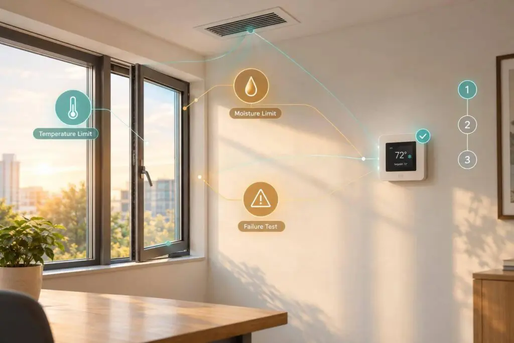
I test window and HVAC controls together before changing how they run. My rule: keep comfort cooling off until every linked window is confirmed closed, while preserving required ventilation, moisture control, and safety protections.
I check three things:
- Signals: Does feedback confirm what windows and equipment actually do – not just what they’re told to do?
- Control rules: Do temperature, moisture, and timing limits prevent conflicting actions? A 55% RH warning and 60% RH protective trigger are starting points to test, not universal settings.
- Failures and results: Do stuck windows, lost signals, and closure delays trigger the right response without failing comfort or airflow limits?
Lower energy use alone isn’t a pass. I compare seasonal results under matched conditions, document the settings, and <u>verify shutdown and restart in the building</u> before accepting the controls.
VT5.9 Creating Mixed Mode HVAC Schedules in EnergyPlus
Step 1: Model Window Sensors and HVAC Signals
Build a zone-to-equipment map that links each window ID to its zone and any shared air handler, compressor, boiler, or heat pump. This lets the simulation flag open-window and HVAC conflicts by zone.
Label each link as direct, shared, or indirect. Record any limits that prevent conditioning one zone without affecting the rest of the system. The map provides a signal path for each conflict.
Track Window Position, Temperature, and Humidity
Map window feedback to open/closed for contact switches or 0%–100% open for continuous position readings. For each point, record the source, units, update interval, and quality flag. Also track time since the last valid update so old feedback doesn’t pass as current.
Track indoor and outdoor dry-bulb temperature, relative humidity, and calculated dew point or humidity ratio. Outdoor relative humidity alone doesn’t show incoming moisture, because it changes with temperature. To check condensation risk, compare indoor dew point with interior surface temperatures. Include occupancy, CO₂, and outdoor air quality only when they affect ventilation logic.
Align Signal Timing and Test Sensor Failures
Place window feedback, heating and cooling demand, enable commands, compressor or valve status, fan proof, supply-air temperature, and airflow on a single timestamped timeline.
Choose a control timestep short enough to resolve the shortest modeled delay. Model closure confirmation and startup delay as separate events. Enable commands are requests – not proof of operation. Verify equipment proof signals and supply-air response before counting HVAC operation while a window is open.
Test stuck-open and stuck-closed contacts, intermittent signals, stale temperature or humidity readings, communication loss, missing equipment proof, and windows that stay open after a close request.
Flag each point as Normal, Stale, Failed, or Uncertain. Give each failure an alarm and a fallback:
For a failed humidity sensor, use a conservative fallback or backup sensor rather than assuming humidity is safe; a failed window sensor may require affected-zone cooling inhibition while preserving required ventilation, freeze protection, and other required overrides.
Any authorized override should expire automatically. Use these signals to define the window-close and cooling-lockout rules in Step 2.
Step 2: Set Window and Cooling Mode Rules
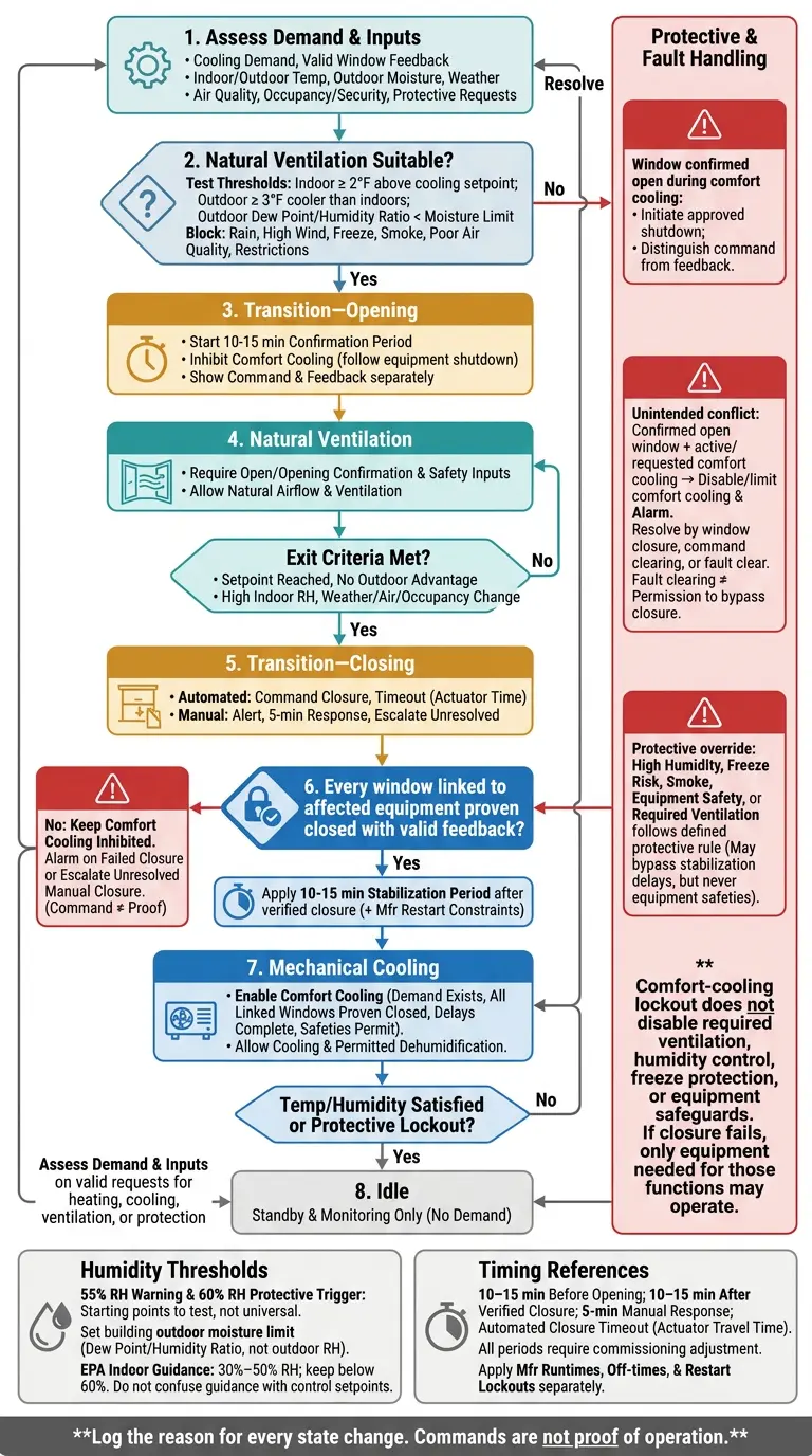
Window and HVAC Interlock: Safe Cooling Restart
Use the sensor feedback and failure flags from Step 1 to decide when natural ventilation is allowed and when comfort cooling must remain locked out.
Set Temperature and Moisture Limits
In the simulation, allow natural ventilation only when there’s cooling demand and outdoor air can help cool the building. Start with adjustable thresholds: indoor temperature at least 2°F above the cooling setpoint, outdoor temperature at least 3°F cooler than indoors, and outdoor dew point or humidity ratio below the building’s moisture limit.
Set the moisture limit for the building – don’t use a universal value. Base it on dew point or humidity ratio, not outdoor relative humidity alone. EPA recommends indoor relative humidity of 30%–50%, kept below 60%.
Exit natural ventilation when the cooling setpoint is reached, the outdoor cooling advantage disappears, indoor relative humidity reaches its high limit, or rain, poor outdoor air quality, or occupancy restrictions change. Block window opening during rain, high wind, freezing risk, smoke, poor outdoor air quality, or occupancy and security restrictions.
Use separate entry and exit thresholds so small temperature changes don’t cause repeated mode switching. When any limit is crossed, the simulation must follow the closure rule before re-enabling cooling.
Verify Window Closure Before Cooling
When a window is confirmed open, stop comfort cooling, such as a ductless mini split, through the equipment’s approved shutdown sequence. Keep required ventilation, humidity control, freeze protection, and equipment safeguards separate from this lockout.
A 55% RH warning and 60% RH protective override can trigger window closure and moisture-control operation. If closure fails, issue an alarm and keep comfort cooling disabled. Only equipment needed for humidity control, freeze protection, ventilation, or equipment safety may operate.
For automated windows, command closure and require valid closed feedback from every window linked to the affected equipment before enabling comfort cooling. Base the closure timeout on the actuator’s documented travel time.
For manual windows, alert occupants and allow a 5-minute response period. If closure remains unresolved, escalate to a building operator.
Define Control States and Switching Delays
Use the table below as the simulation’s control logic. Start with a 10- to 15-minute confirmation period before opening and a 10- to 15-minute stabilization period after verified closure. Adjust both during commissioning.
Protective requests may bypass comfort stabilization delays, but never equipment safeties. Apply manufacturer-specified minimum runtimes, minimum off-times, and restart lockouts separately. Log the reason for every state change.
| State | Entry trigger | Required window feedback | Allowed equipment operation | Exit condition |
|---|---|---|---|---|
| Natural ventilation | Indoor temperature exceeds the cooling threshold and outdoor air is suitable | Open or opening confirmed; safety inputs normal | Natural airflow; required ventilation equipment | Cooling setpoint reached, humidity high limit, weather restriction, or occupancy change |
| Mechanical cooling | Cooling demand exists and windows are proven closed | Closed confirmation required | Comfort cooling and permitted dehumidification | Temperature and humidity satisfied or protective lockout |
| Idle | No active temperature or moisture demand | Any, subject to alarms | Standby and monitoring only | Valid heating, cooling, ventilation, or protection request |
| Transition – Opening | Cooling demand and favorable outdoor conditions initiate handoff to natural ventilation | Opening command and position feedback | Comfort cooling inhibited before window opening | Window proven open and conditions stable, or opening fails |
| Transition – Closing | Cooling or humidity demand requires handoff from natural ventilation | All linked windows proven closed | Comfort cooling inhibited until closure and delay complete | Closure and delay complete, closure fails, or protective override changes |
| Protective override | High humidity, freeze risk, smoke, equipment safety, or required ventilation | Per protective rule above | Per protective rule above | Protective condition clears |
| Unintended conflict | Open window plus active or requested comfort cooling | Confirmed open window and cooling status or command | Disable or limit comfort cooling; alarm | Window closes, cooling command clears, or operator clears the fault |
Step 3: Test Conflicts and Failures in Simulation
Use the control rules from Step 2 to stress-test the model with weather swings, delays, and signal failures.
Test Open Windows and Weather Changes
Test four cases: cooling with windows closed, natural ventilation with windows open, open-window cooling when outdoor conditions meet the cooling criteria, and open-window heating during a cool period. These tests check whether the model stops comfort HVAC when window status changes.
Repeat the tests during occupied and unoccupied periods, including high outdoor moisture and sharp temperature changes. Set a temperature and humidity recovery deadline before testing. Mark a run unsuitable as soon as conditions violate the defined limits. Check whether temperature and humidity recover by the deadline, and verify airflow in cfm against the project requirement.
Inject stuck-open, stuck-closed, intermittent, and stale window signals. Add conflicting building automation system (BAS) commands and delayed HVAC shutdowns. These faults should trigger the lockouts defined in Step 2. Test occupant closure delays of 2, 5, and 15 minutes.
Use independent position feedback to detect false contact readings. Without that feedback, document the fault the controller cannot detect. Check whether each failure triggers the expected lockout or fallback.
Check Results Against Expected Responses
Define pass/fail limits before testing: shutdown latency, recovery time, temperature range, humidity limit, minimum ventilation airflow, and allowed hours outside the comfort band. A blocked cooling request is a correct protective response – not equipment operation.
| Test trigger | Expected response | Simulated response | Pass/fail |
|---|---|---|---|
| Cooling demand; windows proven closed | Interlock permits cooling; proof signal confirms operation | ||
| Window opens during comfort cooling | Interlock initiates approved shutdown; proof signal confirms shutdown by the response deadline | ||
| Outdoor moisture becomes unsuitable | Natural ventilation ends; closure and moisture-control rules take priority | ||
| Window remains open during heating | Apply the heating interlock; permit heating only under the defined closure or override rules | ||
| Contact fails or BAS commands conflict | Record a fault, notify the operator, and apply the defined fallback | ||
| Occupant closure exceeds the response period | Escalate the alert; maintain the required lockout |
Record conflict count and duration, heating and cooling runtime, fan runtime, temperature, RH, ventilation airflow, hours outside the comfort band, and energy use.
Use each event’s cause, equipment feedback, and outcome to separate authorized protective operation from unintended conflicts. Lower energy use does not make a run acceptable if it fails comfort, moisture, or ventilation criteria.
Review Timelines and Seasonal Performance
Plot window status, temperatures, humidity or dew point, occupancy, commands, feedback, airflow, alarms, and mode changes on one timeline. Use one-minute reporting where adequate, with finer logging for shorter delays.
After the fault cases pass, compare seasonal performance under matched assumptions. Use identical weather, loads, schedules, setpoints, equipment efficiencies, and ventilation requirements, with the same mixed-mode rules. Repeat with different opening patterns, simultaneous openings, sensor delays, and communication outages. Savings remain conditional, not guaranteed.
Comparison worksheet – enter model outputs only after both runs. Each cell should show windows-closed baseline → mixed-mode results.
| Period | Electricity / heating fuel (kWh / therms, if applicable) | Fan operation (hours) | Hours outside the comfort band | Hours above the RH limit |
|---|---|---|---|---|
| Summer | ||||
| Spring and fall | ||||
| Winter | ||||
| Annual |
Conclusion: Verify Controls Before Field Use
A passing simulation proves the logic – not the installed system. Field acceptance must check window feedback and confirm that equipment actually shuts down and restarts. Reproduce the open-window/HVAC conflicts flagged in simulation. Check that interlocks prevent unintended cooling with windows open while preserving required ventilation, freeze protection, fire and smoke sequences, and equipment safeties. Use the same limits and interlocks in commissioning records and onsite tests.
Document Settings and Commission the System
Record each sensor’s location, communication method, normal state, and behavior when it fails. Document zone equipment assignments; indoor temperature and humidity limits; outdoor temperature, moisture, and air-quality limits; closure and restart delays; manual overrides; alarm priorities; and seasonal schedules.
Keep the sensor map, threshold table, equipment-zone matrix, trend logs, alarm and override records, failed-test resolutions, and signed results. These records support onsite checks of the simulated logic.
Next, test the interlock in the field. Check windows when open, closed, partially open, and partially latched. Reopen them during cooling, and disconnect representative window contacts or sensors. Confirm that affected equipment stops and restarts under approved conditions – not just that its command changes.
Not every thermostat supports open-window interlocks. Document unsupported functions and identify who can approve time-limited overrides for unresolved manual-window conflicts. An open window alone does not prove adequate ventilation; verify required airflow during field testing.
FAQs
Can my existing HVAC system support window interlocks?
Most existing HVAC systems can support window interlocks with building automation or smart control upgrades. Eco Temp HVAC can check your system’s compatibility and connect window sensors to compatible controls. These controls automatically pause mechanical heating or cooling when windows are open.
If a direct connection isn’t possible, wireless IoT sensors and advanced control upgrades can often deliver the same energy savings – without replacing your core HVAC equipment.
How do window interlocks work with shared HVAC equipment?
Window interlocks link automated window sensors or motorized dampers to the HVAC control system. When a sensor detects an open window, the system adjusts HVAC settings – usually by pausing heating or cooling in that zone while natural ventilation is in use. This prevents the equipment from working against air flowing through the open window, helping keep the space comfortable and cut energy waste.
How should I set humidity limits for my building?
Balance occupant comfort, building material protection, and energy efficiency. Set humidity targets for each zone within owner-approved limits, then check performance with measurements that represent conditions in those zones.
Model temperature control and moisture removal separately. Hitting a temperature target doesn’t mean humidity is under control. Smart thermostats and building automation can help maintain humidity levels and improve comfort. They may also allow higher temperature settings and lower energy use.