
A tankless water heater in a condo, duplex, or apartment building is not a simple swap. Before I pick a unit, I need to check 12 things: venting, gas capacity, electrical load, fire-rated walls, condensate drainage, unit location, hot-water demand, recirculation, service access, noise, permits, and tenant access.
Here’s the short version: a gas tankless unit may need 90,000 to 130,000 BTU/hour, and some units go up to 199,000 BTU/hour. That can strain shared gas lines fast. Output also depends on GPM + temperature rise. So if incoming water is cold, the same heater delivers less hot water. And if I skip venting, drain routing, or clearance checks, I can end up with failed inspections, shutdowns, wall openings, or resident complaints.
If I want a successful water heater installation, I need to confirm:
- Vent route: length, elbows, terminations, windows, balconies, and rated walls
- Gas service: pipe size, run length, meter capacity, regulator settings, and total BTU load
- Electrical: voltage, amps, breaker space, panel load, and any pump power
- Wall and fire issues: penetrations, shafts, corridors, and firestop details
- Condensate drain: slope, material, freeze risk, neutralizer, and pump if needed
- Location: service space, shutoffs, and a way to remove the unit later
- Peak demand: fixture count, occupancy pattern, inlet water temperature, and setpoint
- Piping and recirculation: loop length, pump sizing, insulation, and balancing
- Maintenance access: filters, valves, vent parts, and access panels
- Noise: bedrooms, party walls, vibration, and pipe support
- Permits: plumbing, gas, electrical, firestopping, and inspections
- Tenant impact: notices, shutoff windows, keys, staging, and backup hot water
Ultimate Guide to Choosing Tankless Water Heaters: Installation, Costs & Benefits Explained
Quick Comparison
| Setup | Main sizing focus | Main access issue | Main outage risk | Main piping issue |
|---|---|---|---|---|
| Individual unit | One dwelling’s peak fixtures + temperature rise | Entering occupied units for service | Usually one home at a time | Shorter runs, less recirculation in many cases |
| Centralized system | Building demand + staging + recirculation losses | Mechanical-room layout and rack service space | Many homes can lose hot water at once | Return loops, balancing, pump control, insulation |
My bottom line: I would never choose the heater first. I would check the building first, document the limits, and size the system from actual peak demand at the building’s coldest inlet-water temperature.
Quick Planning Snapshot
Use this table before installation to check what matters, what you need to collect, and what can go wrong if you skip a step. It works for both layouts. The difference is how each issue shows up in practice.
| Planning Category | Main Constraint to Verify | What to Gather | If Skipped |
|---|---|---|---|
| Venting path | Listed vent system, route, listed or equivalent length, termination clearances, and whether existing venting can be reused | Equipment installation manual; route sketch; measured length and fittings; termination photos | Unsafe or noncompliant exhaust, redesign, added construction, or failed inspection |
| Gas line and capacity | Pipe diameter, developed length, supply pressure, meter or regulator capacity, and combined BTU/h load across all appliances served | Gas utility information; appliance schedule; pipe measurements; pressure test or contractor assessment | Low input, unreliable operation, nuisance shutdowns, or required gas-service upgrades |
| Electrical service | Voltage, amperage, grounding, and whether a dedicated circuit is required for the heater, controls, pumps, or freeze protection | Panel schedule; voltage and amperage measurements; electrician’s load calculation | Tripped breakers, failed ignition or controls, unsafe wiring, or panel or service upgrades |
| Shared walls and fire separations | Rated assemblies, penetrations, shaft requirements, and fire-stopping details | Building plans; rated-wall details; field inspection; fire-stopping specifications | Loss of fire rating, failed inspection, or smoke- or fire-compartmentation concerns |
| Condensate and drain access | Approved drain route, discharge point, pipe material, slope, neutralizer requirement, and any condensate pump or pressure-relief discharge route | Drain-location measurements; plumbing plans; equipment manual; local code review | Water damage, corrosion, freezing, blocked operation, or code violations |
| Unit placement | Code-compliant mounting surface, required clearances, combustion-air requirements where applicable, and protection from freezing | Clearance dimensions from installation manual; wall-construction notes; field measurements | Noncompliant installation or forced entry into tenant spaces for routine service |
| Peak hot-water demand | Simultaneous peak flow at the building’s lowest expected incoming-water temperature | Fixture counts and flow rates; occupancy data; incoming-water temperature; desired outlet temperature | Undersized output, cold-water complaints during morning peaks, or costly equipment replacement |
| Recirculation and water piping | Loop length, return-pipe location, pump and controls, check valves, insulation, and expansion-control requirements | Plumbing riser diagrams; pipe-size measurements; fixture distances; existing loop condition | Slow hot-water delivery, increased energy use, or extensive wall and ceiling access for corrections |
| Maintenance and replacement access | Service clearances, access-panel dimensions, shutoff locations, filter locations, warranty requirements, parts availability, maintenance intervals, and the path for removing the unit | Field measurements of clearances; access-panel sizes; path sketch for unit removal; warranty documents; equipment serial numbers; maintenance schedule | Technicians forced to remove finished surfaces or enter occupied units for routine maintenance, voided warranties, or delayed emergency repairs |
| Noise and vibration | Proximity to bedrooms, living areas, party walls, and fire-rated corridors; mounting isolation | Wall-construction type; room-use notes; equipment vibration specs | Fan, burner, pump, or water-hammer noise transmitted to occupied spaces |
| Permits and inspections | Local authority having jurisdiction requirements for mechanical, plumbing, electrical, gas, fire-stopping, and building codes | Prior permit records; AHJ contact; adopted code editions; fire-stopping product specs | Delayed occupancy approval, stop-work orders, or costly corrective work |
| Tenant disruption and building access | Notice periods, shutoff windows, elevator and hallway rules, contractor access hours, parking or staging requirements, and temporary hot-water provisions | Building rules; lease terms; utility-shutoff procedures; tenant contact list | Missed appointments, extended outages, tenant complaints, or unsafe work in occupied areas |
On paper, this can look like a simple checklist. In the field, it rarely is. A vent route that works for one layout may be a headache for the other. The same goes for gas piping, service access, and how much disruption tenants will tolerate.
That’s why these planning items matter up front. In individual-unit systems, access and unit placement often drive the job. In centralized systems, demand, recirculation, and utility capacity usually take the lead. The next section looks at those tradeoffs side by side.
1. Confirm the Venting Path
Venting usually creates the first hard limit on where a tankless unit can go.
Installation constraint
Every indoor gas tankless water heater needs its own exhaust path and combustion-air path. Most condensing models use sealed direct venting through a side wall or the roof.
Use the manufacturer’s max equivalent length and elbow limits. A few extra turns can eat up the allowed run fast. Vent material also depends on the model, so check the installation manual to confirm which materials are approved.
Why it matters in multi-family buildings
In multifamily buildings, venting gets tight fast because of shared walls, balconies, windows, and air intakes. A termination point that looks fine on a plan can end up directly below another unit’s operable window or right next to a mechanical air intake. That isn’t just annoying. It’s a safety issue if combustion exhaust can enter a neighboring unit.
If the vent passes through a fire-rated assembly, you’ll need listed firestopping and the right approvals. For centralized or cascading systems, the design also has to account for combined input, total equivalent length, and termination clearances.
Measurements or documents to review
Start with the exact installation manual for the heater model you’re considering. You’ll also want a scaled floor plan and elevation that shows the full vent route, including every elbow, wall penetration, shaft, and termination point.
Existing building plans should also show:
- Fire-rated assemblies
- Corridors
- Balconies
- Windows
- Outdoor-air intakes
These details can decide where the vent may legally terminate.
In snow-prone areas, keep the termination above the highest expected snow level and check local clearance rules.
Practical owner or manager action
Ask the installer for a written venting sketch before any equipment is bought. That sketch should show the heater location, intake and exhaust routes, pipe sizes, equivalent vent length, elbow count, termination clearances, and any penetrations through rated walls or floors.
If the route goes through a shared wall, common shaft, or roof space, have a licensed contractor and the local mechanical inspector review it before work starts.
Once the vent is installed, but before walls or ceilings are closed, photograph and label the full run. Keep that as-built record with the property’s maintenance files. It makes later service and replacement much easier in occupied buildings.
Once the vent path is set, check whether the gas line can support the heater’s load.
2. Check Gas Line Size and Capacity
Installation constraint
After venting, gas capacity is the next hard limit. A tankless heater can pull 90,000–130,000 BTU/hour, which is much higher than a standard tank heater. The final pipe size depends on the developed length, the number of fittings, and the total connected load.
Why it matters in multi-family buildings
In multi-family buildings, one high-input heater doesn’t just affect one apartment. It can affect gas appliances across several units. Furnaces, boilers, ranges, dryers, fireplaces, and existing water heaters may all share the same meter and trunk line. If one or more high-input tankless heaters are added without recalculating the full system load, the result can be pressure drops, ignition failures, error codes, or uneven operation across the building.
Longer runs make this tougher. So do multiple tankless units. Pressure loss adds up fast, and in multi-unit setups the connected load can get big in a hurry. That means the meter, regulator, and building piping all need to be checked for enough capacity under simultaneous demand.
For natural gas, you can estimate demand in cubic feet per hour (CFH) by dividing the appliance’s BTU/hour rating by about 1,000 BTU per cubic foot. A 199,000-BTU/hour tankless unit works out to about 199 CFH. Two of those units equal about 398 CFH before you even add furnaces, ranges, or any other gas loads.
Documents to collect and verify
Before any work is approved, require the contractor to submit a written gas-load calculation. That paperwork should show:
- The proposed heater’s model number, maximum BTU/hour input, minimum and maximum inlet pressure, required pipe size, regulator needs, and approved gas type from the manufacturer’s installation manual
- Existing meter capacity, regulator settings, and current gas-service pressure
- Pipe material, diameter, and approximate run lengths throughout the building
- Input ratings for every other gas appliance served by the same meter
- Total connected load in CFH, the longest pipe run from meter to the most remote outlet, and any meter or service upgrades that may be needed
Then verify the total demand, the meter capacity, and the regulator output under simultaneous load. It’s also smart to ask the gas utility to confirm capacity when multiple appliances are running at the same time.
Once gas capacity is confirmed, move to electrical service requirements.
3. Plan for Dedicated Electrical Service
Installation constraint
Gas tankless heaters still need electricity. They use power for ignition, controls, sensors, and sometimes a recirculation pump. Electric tankless units are a different story. They pull much more current and can trigger major circuit or service upgrades.
The main issue is the total connected load. The circuit, panel, and service all need to support the heater and any accessories tied to it.
Why it matters in multi-family buildings
In multifamily buildings, electrical load adds up fast. Multiple heaters, pumps, and shared building equipment can push a panel or service past its limit. Electric tankless units can increase that load sharply.
That’s why the exact model matters so much. Before rough-in starts, the team needs to check the heater itself and the building’s full load.
Measurements or documents to review
Before approving the installation, gather the exact model’s installation manual, rating plate, and wiring diagram. Then record:
- Required voltage and frequency
- Maximum amperage and wattage
- Breaker size and quantity
- Conductor type and size
- Grounding method
- Whether the unit uses a plug or needs hardwiring
- Any pump or control loads
The table below shows how electrical needs can differ by heater type:
| Heater type | Voltage | Typical draw | Breakers needed |
|---|---|---|---|
| Gas tankless unit (with or without pump) | 120 V, 60 Hz | Low | Verify per model manual |
| Electric tankless unit | 240 V | High – varies by kW rating | One or more breakers; verify per model manual |
Practical owner or manager action
Have a licensed electrician complete a full load calculation before any equipment is ordered. That review should include the heater, all accessories, and every other load on the affected panel, such as HVAC service needs, laundry, and common-area equipment. The goal is simple: protect the building’s current circuits while adding the new installation.
One detail trips people up all the time: open breaker spaces do not mean the panel has capacity.
Some gas-fired models can plug into a nearby properly grounded receptacle instead of using a dedicated branch circuit, but that depends on the model, accessories, and local code. Confirm the plan with the electrician and the authority having jurisdiction before rough-in begins. Then document the final circuit, breaker size, and conductor specification in the building’s maintenance file.
After electrical capacity is confirmed, review shared walls and fire separations.
4. Review Shared Walls and Fire Separations
Installation constraint
After you sort out venting, check whether the wall itself can handle the heater and all required penetrations. In multifamily buildings, the mounting wall may be a fire-resistance-rated assembly. That changes the job. Every penetration and fastener has to maintain that rating.
Through-penetrations of fire-rated walls require a listed firestop system with an F-rating that matches the wall rating. Use a listed firestop system that fits the wall assembly, the penetrant, the opening size, and the way it will be installed.
Why it matters in multi-family buildings
In a multi-family property, a gap around a vent or pipe isn’t just a sloppy install. It can let fire and smoke move from one unit to another or into an exit path.
That’s why it helps to treat any shared wall as a rated assembly first and a mounting surface second.
A mechanical closet, exterior wall, or service chase can cut down on penetrations and make plan review easier.
Measurements or documents to review
Start with the approved architectural and life-safety plans, the wall-type schedule, and any prior permit drawings. Confirm:
- The required wall rating
- Whether the wall is load-bearing
- Whether the route crosses a shaft, corridor, stair enclosure, or exit access
Then map every penetration the install will need, including:
- Vent
- Gas line
- Hot- and cold-water piping
- Recirculation line
- Condensate drain
- Pressure-relief discharge
- Electrical conduit
- Control wiring
- Equipment-support fasteners
Don’t assume a small opening gets a pass. The authority having jurisdiction decides whether firestopping is required.
Practical owner or manager action
Require the contractor to name the applicable UL 1479 or ASTM E814 firestop system and confirm that it is approved for the actual wall construction and penetrant before any cutting starts. Ordinary caulk or foam should not be used unless the listed system specifically permits it.
Take photos of all concealed work before the wall is closed. Then keep the firestop listing, product data sheets, installation photos, inspection record, and permit documents in the building’s maintenance files.
If the planned wall can’t handle the needed penetrations or service clearances, have the contractor propose another location before work begins, not after.
Next, verify condensate and drain access.
5. Plan Condensate and Drain Access
Installation constraint
If the chosen model is a Navien condensing tankless water heater, condensate drainage becomes the next site limit. This applies only to condensing units, which produce acidic condensate that must drain to an approved location.
Use PVC, CPVC, or another approved corrosion-resistant tube or pipe. Do not use metal pipe. The line needs a continuous slope of 1/4 inch per foot for gravity drainage, and the condensate outlet should stay at 1/2 inch.
If gravity drainage won’t work, install a condensate pump sized for the heater’s discharge. Put it in a spot that can be reached for service.
Why it matters in multi-family buildings
A blocked or frozen condensate line can back up into the unit and shut down hot water service. In a shared setup, one drain problem can affect multiple apartments.
The riskiest runs are often the ones nobody sees. A hidden line above a ceiling or inside a shared wall may seem tidy on day one, but if it leaks or backs up over a finished hallway or a tenant’s unit, repairs can mean opening walls and disrupting residents.
Measurements or documents to review
Before you approve the location, check the installation manual, plumbing plans, drain riser diagrams, and as-built drawings. Then verify:
- Distance and elevation from the outlet to the nearest approved drain
- Whether a continuous 1/4-inch-per-foot slope is possible
- Whether a neutralizer is required by local code or the manufacturer, especially if condensate will enter a metallic drain system
- Whether any unheated or exterior route could freeze
For multiple heaters on a rack or shared setup, the plumbing contractor needs to calculate the combined condensate volume and size the manifold and pump to match. Don’t assume several 1/2-inch drains can just be tied together and left alone.
Practical owner or manager action
Require a written condensate plan before work starts. It should show the appliance, drain route, pipe material and size, slope, neutralizer location if needed, pump model if needed, termination point, and freeze protection method.
One point is non-negotiable: the condensate line and the temperature-and-pressure relief valve discharge line must remain separate. They should never be combined.
During commissioning, confirm that condensate flows freely to the drain. If a pump is installed, test it. Take photos of the finished drain route before walls are closed, then keep those photos in the building’s maintenance file with the neutralizer product data sheet and the pump model number. Also set a schedule to replace neutralizer media at the interval listed by the manufacturer.
Once the condensate route is sorted out, move to unit placement and service clearances.
6. Choose a Unit Location That Allows Servicing
Installation constraint
The unit location needs to support safe installation and later service. As a baseline, plan for at least 30 inches wide by 30 inches deep of clear working space on the service side, unless the model manual or local code calls for more. Always use the exact clearance diagram in the model’s installation manual. Clearances change from one unit and setup to another.
Once the spot works from an access standpoint, the next step is simple: make sure the unit can still handle peak demand.
Why it matters in multi-family buildings
Bad access adds time, hassle, and cost to every service visit. And in a multi-family building, that doesn’t just affect one person. If one heater serves several apartments or shared spaces, any delay can hit multiple residents at the same time.
It also pays to think past installation day. Plan for both service access and full replacement removal before you lock in the location. A unit that goes in during construction can become a headache later if there’s no clear way to get it back out.
Measurements or documents to review
Before approval, gather:
- The model manual
- The floor plan
- Access dimensions
- Structural notes
- The replacement path
Practical owner or manager action
Require the installer to submit a dimensioned location plan before work starts. That plan should show the unit location, service clearances, access route, shutoffs, disconnect, connections, and removal path.
If the heater will sit inside a tenant’s unit, sort out the service process in advance. That means advance notice, appointment windows, key or lockbox rules, floor protection, and a temporary hot-water shutdown plan. When the layout allows it, a dedicated mechanical room or secured utility closet is usually the better choice.
After the location is set, confirm that the system still matches the building’s hot-water load.
7. Calculate Peak Hot-Water Demand
Installation constraint
Peak hot-water demand is not the total hot water used over a full day. It’s the highest amount the building, or the part of the building served by the system, may need at one time.
Start with a full fixture and appliance inventory for the apartments, common areas, and any laundry or commercial spaces tied to the system. Then estimate which fixtures are likely to run at the same time and add up their flow rates in gallons per minute (GPM).
Temperature rise is the difference between the coldest expected inlet-water temperature and the delivery setpoint. In cold-climate projects, size the system for the coldest expected winter inlet temperature, not the yearly average. Then check the manufacturer’s flow table at the project’s actual temperature rise.
Why it matters in multi-family buildings
In a multi-family building, hot-water draws often overlap. Morning showers, kitchen faucets, dishwashers, and laundry can all hit at once. If the system is too small, you get temperature drops, tenant complaints, and short-cycling. If it’s too large, equipment and installation costs go up.
This gets even more serious with centralized systems. One undersized plant can leave a whole building short on hot water during a predictable peak.
Measurements or documents to review
Before you approve any equipment proposal, gather these items:
- Fixture schedule: showers, tubs, lavatory faucets, kitchen sinks, dishwashers, clothes washers, laundry rooms, common-area kitchens, and any commercial fixtures, with rated GPM for each
- Occupancy and use profile: Student housing, senior housing, and typical apartments do not peak the same way
- Coldest design inlet-water temperature for the property’s location
- Target delivery temperature and the resulting temperature rise (ΔT = setpoint − incoming)
- Manufacturer performance tables showing GPM at multiple temperature-rise conditions, not just the advertised maximum
Practical owner or manager action
Ask the installer for a written peak-demand calculation, not just a recommendation based on apartment count. That calculation should show the design GPM, inlet-water temperature, target temperature, ΔT, number and model of units, and unit capacity at that ΔT. It should also test a realistic coincident peak, such as morning showers, kitchen use, and laundry.
If you’re replacing an existing system, compare that calculation with maintenance records, hot-water complaint logs, and peak-hour temperature data. That paper trail can show whether the original sizing assumptions were too low and help you avoid making the same error again.
Once peak demand is set, verify recirculation and piping losses so hot water gets to fixtures fast enough.
8. Plan Recirculation and Water Piping
Installation constraint
Once peak demand is set, the next step is simple: check how far hot water has to travel and whether the building needs recirculation at all.
A system can look fine on paper and still feel too small in day-to-day use if residents have to wait too long for hot water. That’s why you need to decide early whether the building should use a dedicated return loop, demand-controlled recirculation, separate loops, or no recirculation.
For central systems, the pump should not run nonstop. Controls should respond to both a demand signal and loop temperature instead. Place the water heater or central plant as close as practical to the fixtures people use most, keep the recirculation loop close to the units it serves, and don’t oversize the piping if a smaller code-compliant size will do.
In larger buildings, two balanced loops may fit better than one long loop. DOE guidance recommends keeping the water volume between the loop and the farthest fixture to no more than 1 gallon where feasible. Balanced piping also makes service work less of a hassle later, since valves, pumps, and strainers stay easier to reach.
Why it matters in multi-family buildings
Even a correctly sized heater can fall short when piping runs are long or the loop is out of balance.
In apartment buildings, poor circulation usually shows up fast: some units get hot water sooner, others wait, and energy use climbs. When circulation is unbalanced, the apartments farthest from the source tend to have the longest delays. Some manufacturer guidance also sets a limit of 300 feet for total external distribution and return piping, so check the exact limit in the installation manual before signing off.
Measurements or documents to review
Before approving any piping proposal, review:
- Plumbing riser diagrams and pipe specs for supply, return, branches, valve locations, and fixture groups
- Calculated water volume from the recirculation loop to the farthest fixture in each zone
- Pump flow and total dynamic head calculation, not just the heater’s rated GPM
- Manufacturer’s recirculation requirements: allowable return temperature, maximum piping length, minimum flow, and approved connection arrangement
For insulation, DOE guidance recommends at least R-4 on the recirculation loop.
Practical owner or manager action
Require a written commissioning report after start-up that confirms pump rotation and flow direction, supply and return temperatures, balancing valve settings, and hot-water delivery time at the farthest apartment.
Also ask for an as-built riser diagram, labeled shutoffs, and a service schedule for pumps, sensors, balancing valves, and strainers.
Then watch delivery times and loop temperatures during the first few months. If one zone lags behind another, have the system adjusted. After the loop is balanced, keep service access clear.
9. Keep Maintenance and Replacement Access Clear
Installation constraint
Check two things before you lock in the location: service clearance and a clear removal path. Use the model’s manual and local code for the exact dimensions. A tankless water heater may fit on a wall and still be a headache to work on.
The unit needs open front access so a technician can reach the controls, filters, valves, connections, and vent. And service space is only half the story. You also need to think about how the unit will come out later.
Before you approve the spot, measure every pinch point between the heater and the building exterior. That includes the closet door, corridor width, stairwell dimensions, elevator size, and any tight turns. The route should let the unit come out without demolition.
Why it matters in multi-family buildings
In multi-family buildings, blocked access can turn a simple service call into long downtime for one unit or even a central system. A location that looks fine on install day may stop working later when storage, piping, or nearby equipment starts eating up the space.
That happens all the time. A heater that was easy to reach at first can turn into a tough repair once shelves, finishes, or new gear crowd the closet.
There’s another issue people miss: the replacement unit may not have the same dimensions or connection points as the old one. Leaving a bit more working room and removal space now can save you from cutting into a wall or ceiling later.
Measurements or documents to review
Before approving the installation location, collect and record:
- The heater’s exact dimensions and the manufacturer’s required top, side, bottom, and front clearances
- The available service-space dimensions at the installation site
- The width and height of the full removal path, including the mechanical-room door, closet opening, corridor, stairwell, elevator, and any turns
- The locations of shutoff valves, isolation valves, unions, service ports, filters, drain connections, electrical disconnects, and vent connections
Don’t rely on a generic clearance number. Code guidance is clear that clearances are determined by the applicable code, the appliance listing, and the manufacturer’s instructions – all three together. Keep both the installation manual and the service manual, since some manufacturers publish them as separate documents.
Practical owner or manager action
Before walls or ceilings are closed, ask the installing contractor to walk through the planned service procedure on-site. That simple step often exposes access problems that look fine on paper.
Take photos of the installation. Label each shutoff and access panel. Then file the make, model, serial number, install date, warranty, fuel type, electrical requirements, vent layout, service clearances, and removal path in the building’s maintenance file.
After turnover, check the access area from time to time. Storage, tenant remodeling, and new services can wipe out clearances faster than you’d think.
With service access set, review how fan, burner, and pump noise will carry through the building.
10. Manage Operating Noise and Vibration
Installation constraint
Once you’ve confirmed service access, check how much sound and vibration could travel into occupied rooms. Tankless water heaters make noise from the fan, burner, pump, and moving water. In residential condensing models, published sound levels often land around 47 to 53 dB, but the way the unit is mounted, plus the framing around it, has a big effect on how much of that sound people actually hear in nearby rooms.
Don’t mount the unit directly against a wall shared with an occupied unit. Also avoid lightweight framing that tends to pass vibration along. Use cushioned pipe clamps, flexible connectors, and resilient supports so pipes, venting, gas lines, and condensate parts don’t touch framing and turn the whole wall into a sounding board.
Why it matters in multi-family buildings
In multi-family buildings, structure-borne vibration is often more annoying than airborne fan noise. A low hum in a utility room might seem minor, but in a bedroom, living room, or hallway, that same vibration can come across as a buzz or rattle.
Measurements or documents to review
Check the manual for mounting limits. Confirm the listed dB rating and the test conditions behind it. Then review architectural or as-built drawings to see where shared walls, bedrooms, and framing lines sit before you approve the location.
Practical owner or manager action
Include noise and vibration control in the bid spec. After installation, listen from the adjacent room during:
- ignition
- steady operation
- recirculation
Testing only at the unit doesn’t tell you much. What matters is what residents hear on the other side of the wall.
If you hear rattling, banging, howling, or shaking, treat it as a service issue, not something to mask with padding. Those sounds usually point to a mounting, pressure, or support problem (or efficiency loss from hard water) that needs to be fixed before residents start filing complaints. Any sound-control work still has to keep vent clearances, combustion air, firestopping, and drainage intact.
It also helps to set expectations. Let residents know a brief fan or ignition sound at startup is normal. Ask them to report new rattling, shaking, or constant humming so maintenance can track down the cause before it turns into a bigger repair.
Once the acoustic layout is set, move to permits and inspections.
11. Pull the Right Permits and Schedule Inspections
Once noise and access are handled, the next step is permits and inspections.
Installation constraint
A multifamily tankless install often needs plumbing, mechanical or fuel-gas, and electrical permits. If the job touches a rated wall, shaft, ceiling, or another building component, you may also need building or fire-department review.
Don’t assume a simple replacement skips this step. In multifamily work, that can come back to bite you. Check with the local building department before work starts so you know exactly what permit package they want.
Why it matters in multi-family buildings
In condos, duplexes, and apartment buildings, one install can affect nearby units, shared utility areas, fire separations, and common gas or electrical systems.
Permits and inspections create a paper trail for the building’s shared systems. They also help confirm that the job meets code for:
- Venting
- Gas
- Electrical
- Condensate
- Firestopping
That matters not just for the install itself, but for future service work too.
Measurements or documents to review
The permit package should include the permit application, floor plan, installation manual, spec sheet, gas-piping diagram, venting plan, and panel schedules.
The manufacturer’s installation manual matters more than many owners expect. Inspectors use it to check clearances, venting, and condensate requirements. In plain English: the paperwork needs to match what’s actually being installed in the field.
Practical owner or manager action
Schedule rough inspections for plumbing, gas, electrical, venting, and firestopping before walls close. Then schedule the final inspection after startup.
It also helps to confirm the local inspection-request deadline ahead of time. Miss that cutoff, and the whole job can slide.
After permitting is locked in, plan tenant notice and shutdown windows around the approved schedule.
12. Plan for Tenant Disruption and Building Access
Once permits and inspections are on the calendar, the last big piece is access and tenant notice.
Installation constraint
A tankless water heater install is not just a basic appliance swap. Techs may need to get into apartments, utility rooms, common areas, rooftops, exterior walls, panels, and shutoffs. If piping, venting, or wiring runs between floors, they may also need access to units above or below.
Before you lock in a date, make an access map. Spell out every space the crew may need to enter and note whether a resident has to be there or if master-key access is allowed under the lease.
In a multifamily building, that access issue can hit more than one household at the same time.
Why it matters in multi-family buildings
In a condo, duplex, or apartment building, one installation can affect several households at once. A centralized or riser-connected setup can interrupt service in multiple apartments and common areas. And if hidden piping problems show up behind walls or between floors, outages can drag on longer than planned.
Written notice should include:
- The purpose of the work
- The date and time
- The spaces affected
- The expected duration
- Any water, gas, or electrical interruptions
The notice period also needs to match the lease and local law.
Measurements or documents to review
Review the building’s unit schedule, floor plans, riser diagrams, domestic-water shutoff locations, and electrical-panel schedules. Also document how many apartments are affected and any access limits.
The written scope should clearly state who will get permits, set inspections, handle testing, and finish punch-list repairs.
Practical owner or manager action
Put one manager or superintendent in charge as the project contact. Give the contractor keys, access codes, parking details, elevator reservations, and allowed work hours before the job starts. Check whether the building also requires certificates of insurance, sign-in rules, or union coordination.
It also helps to phase the work one unit or one stack at a time instead of shutting down the entire building. Leave extra time in the schedule for material delays or hidden piping issues. If a long outage looks likely, line up a plan for temporary housing or backup hot water.
Keep permits, approvals, startup records, tenant notices, and outage logs on file for later service needs and dispute resolution.
With access planned, compare individual-unit and centralized layouts.
Individual Unit vs. Centralized System: Key Differences
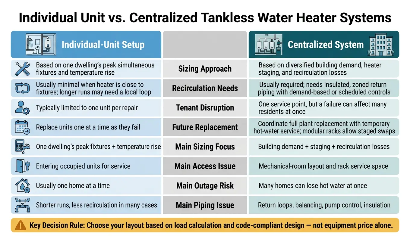
Individual Unit vs. Centralized Tankless Water Heater Systems: Key Differences
Once the building limits are clear, the next call is simple on paper but far-reaching in practice: should the system serve each dwelling on its own, or the whole property from one shared setup?
This isn’t just about upfront cost. It shapes service access, who loses hot water during a shutdown, and how you handle replacement years from now.
Individual-unit systems put one heater in or near each apartment, condo, or duplex unit. Each dwelling runs on its own, so if one heater fails, the problem usually stays inside that single home. That sounds convenient – and often it is. But the property side gets messier. Every dwelling needs its own utility connections and service access, and over time you can end up with a mix of brands, models, and warranty terms if replacements happen at different times.
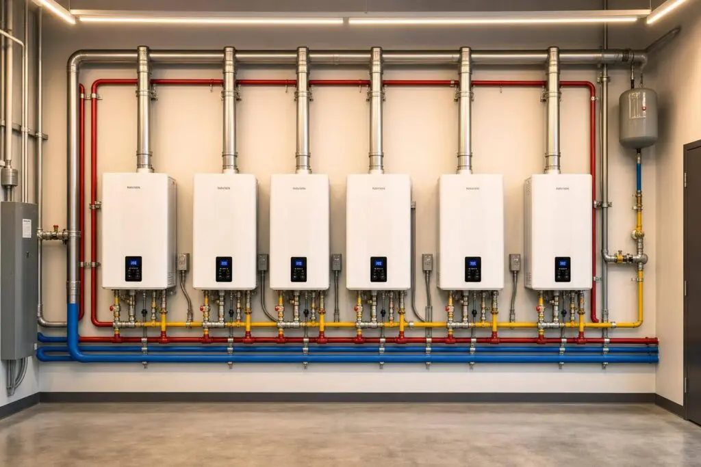
Centralized systems group the equipment in a dedicated mechanical room, often with multiple tankless heaters set up in a cascaded arrangement. That can make service easier because everything is in one place. The downside is obvious: when the system goes down, more residents can be affected at once.
The table below lays out the main planning differences side by side:
| Planning Factor | Individual-Unit Setup | Centralized System |
|---|---|---|
| Sizing approach | Based on one dwelling’s peak simultaneous fixtures and temperature rise | Based on diversified building demand, heater staging, and recirculation losses |
| Recirculation needs | Usually minimal when the heater is close to fixtures; longer runs may still need a local loop | Usually required; needs insulated, zoned return piping with demand-based or scheduled controls |
| Tenant disruption | Typically limited to one unit per repair | One service point, but a failure can affect many residents at once |
| Future replacement | Replace units one at a time as they fail | Coordinate a full plant replacement with temporary hot-water service; modular racks can allow staged swaps |
Pick the layout based on load calculation and code-compliant design, not just equipment price. That choice carries through the whole project, from sizing and recirculation to service access and replacement planning.
Conclusion
These checks tell you something simple but important: can this project actually be built, serviced, and approved?
A tankless water heater can work in a multifamily building, but only if the site can handle its fuel, electrical, venting, drainage, code, and access needs. The mistake people make most often is sizing the unit based on apartment count or the size of the old heater. That’s the wrong yardstick. Size it based on simultaneous fixture demand and the coldest incoming water temperature.
Once you know the system will work, document the site before you order equipment. Take photos of the location. Measure clearances. Verify gas or electrical capacity. Record the vent path, drain access, pipe sizes, and any access limits. That paper trail helps you avoid a bad order and keeps the install safe and legal.
Bring in licensed plumbing, mechanical, gas, and electrical pros from the start. Then, before turnover, set up a service plan that records the model, serial number, warranty, vent components, filter locations, and service schedule.
FAQs
Can I replace a tank water heater with tankless in any apartment building?
No. A tank water heater can’t automatically be swapped for a tankless unit in every apartment building.
It only works if the building can handle peak hot-water demand and the install meets the rules for gas or electrical capacity, venting and condensate routing, unit placement and drain access, and local code and permit approval.
In some multi-family buildings, simultaneous showers and laundry can push demand high enough that you may need one larger unit or multiple units.
How do I know if my building’s gas and electrical service are enough?
Compare your tankless system’s peak hot-water demand with what your building’s utilities can supply.
For gas, many whole-home units need a properly sized gas line, often 3/4-inch. If your home still has an older 1/2-inch line, you may need to upgrade it. That’s one of those details that can trip up a project fast.
For electric, high-demand systems can call for about 200A service, several dedicated 240V breakers, and heavy-gauge wiring. In plain English: the unit may fit on the wall, but your electrical panel still has to handle the load.
Before you lock in the design, confirm local permit and code rules too. It’s a small step that can save you a big headache later.
Should a multi-family property use individual tankless units or one central system?
In most cases, one central tankless system isn’t the best fit if overlapping hot-water demand can push past what a single unit can deliver, especially during colder weather.
A setup with multiple tankless units – often arranged in a cascaded or manifolded system – usually does a better job when several fixtures are running at once. It also gives you some backup if one unit needs service.
The best option comes down to your peak GPM and BTU demand, along with the limits of your gas supply, venting, and electrical setup.