
A bad vent termination can send carbon monoxide back into the building, trip furnace safeties, or fail inspection. In one CPSC review, vented gas appliance CO cases included 51 incidents and 66 vent-related failures tied to blocked, disconnected, or wrong vent setups.
If I were sizing up furnace vent termination options fast, I’d focus on four things first:
- Furnace type: Category I uses Type B metal vent; condensing Category IV uses PVC, CPVC, or polypropylene only.
- Termination path: Roof or sidewall both work, but clearances, snow, and wind often decide the route.
- Vent layout: Two-pipe direct vent gives more routing freedom; concentric kits use one opening but need exact manufacturer approval.
- Code and manual match: The install must match the manufacturer instructions, NFPA 54, IFGC, and local AHJ rules.
Here’s the short version:
- Type B roof terminations are common for non-condensing furnaces and need the right roof height, supports, and 1-inch clearance to combustibles.
- Plastic roof terminations for condensing furnaces must stay above snow level, avoid condensate traps in the run, and often keep intake/exhaust separated.
- Sidewall terminations are common on condensing furnace changeouts, but they must stay clear of windows, doors, air inlets, walkways, and grade.
- Direct-vent systems work best when intake and exhaust end in the same outdoor pressure zone.
- Every elbow, foot of pipe, and slope change matters because vent length and condensate drainage can decide whether the furnace runs right.
Furnace Vent Termination Options: Side-by-Side Comparison Guide
How to Vent Your High Efficiency Furnace!
sbb-itb-b5c10b1
Quick Comparison
| Option | Used for | Usual path | Main checks |
|---|---|---|---|
| Type B metal vent | Category I furnace | Roof | Roof height, 1-inch clearance, bracing, listed cap/flashing |
| PVC / CPVC / polypropylene | Condensing furnace | Roof or sidewall | Manufacturer-approved material, snow height, pitch back to furnace |
| Two-pipe direct vent | Condensing furnace | Roof or sidewall | Separate intake/exhaust placement, spacing, vent length |
| Concentric kit | Condensing furnace | Roof or sidewall | Exact model approval, one-opening layout, kit orientation |
Bottom line: I’d choose the vent termination that fits the furnace category, meets clearance and snow rules, and stays inside the vent table in the install manual.
Vertical Roof Vent Termination Options
Roof termination is often the best path when sidewall clearances are blocked by windows, doors, gas meters, or the way the mechanical room is laid out. Once you decide to go through the roof, the next step is simple: match the vent material, height, and snow clearance to the furnace type.
Type B Gas Vent Roof Terminations for Category 1 Furnaces
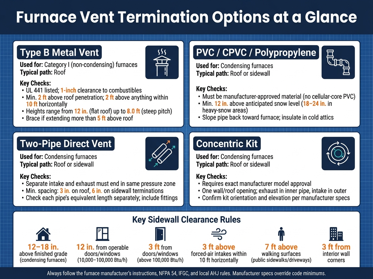
Category I furnaces use listed Type B double-wall metal gas vent under UL 441. This vent keeps a minimum 1 in. clearance to combustibles for the full run. You also need listed roof flashing, plus a storm collar, vent cap, and the required supports to keep the roof penetration weathertight and properly secured.
Height rules matter here. A common baseline is:
- At least 2 ft above the roof penetration
- At least 2 ft above anything within 10 ft horizontally
That said, the manufacturer’s pitch table can call for more. On roofs from flat up to 7/12 pitch, the vent may be allowed as low as 12 in. above the roof. On very steep roofs, the needed height can go up to 8.0 ft. If the vent extends more than 5 ft above the roof, brace it for wind load.
PVC, CPVC, or Polypropylene Roof Terminations for Condensing Furnaces
Condensing furnaces need plastic venting: Schedule 40 PVC under ASTM D1785, CPVC under ASTM F441, or polypropylene listed to UL 1738. The vent material has to be approved by the furnace manufacturer. Cellular-core PVC and non-pressure-rated pipe are often not allowed.
In a two-pipe direct-vent roof setup, the exhaust usually terminates above the intake. Many manufacturers also call for at least 12 in. of vertical separation between the two openings to help prevent recirculation.
Snow clearance is another big one. Both pipes need to terminate above expected snow buildup. Most U.S. manufacturer instructions call for at least 12 in. above anticipated snow level, and some push that to 18–24 in. in heavy-snow areas.
On long vertical runs through an unconditioned attic, don’t let low spots form where condensate can collect. In cold attics, insulate the plastic vent pipe to cut down on condensate and lower the chance of ice blockages.
Roof Vent Comparison: Type B vs. Condensing Vent Materials
| Factor | Type B Metal Vent (Category I) | PVC / CPVC / Polypropylene (Condensing Furnaces) |
|---|---|---|
| Furnace type | Category I, non-condensing | Condensing furnaces |
| Vent pressure | Negative-pressure venting | Positive-pressure venting |
| Moisture handling | Not designed for condensate | Must manage acidic condensate |
| Listed standard | UL 441 | UL 1738 for polypropylene; PVC/CPVC per ASTM D1785 / F441 |
| Clearance to combustibles | 1 in. minimum | Per manufacturer instructions |
| Support hardware | Firestop spacers, roof supports, straps | Pipe hangers or straps at specified intervals; insulation in cold attics |
| Common use case | Category I furnaces | High-efficiency condensing furnaces |
| Snow-level requirement | Height per pitch table and 2+2 rule | At least 12 in. above anticipated snow accumulation |
| Key installation limit | Not for condensing appliances | Material must match furnace approval |
If roof clearances can’t be met, the next step is choosing a sidewall termination or exploring other heating services.
Sidewall Vent Termination Options and Clearance Rules
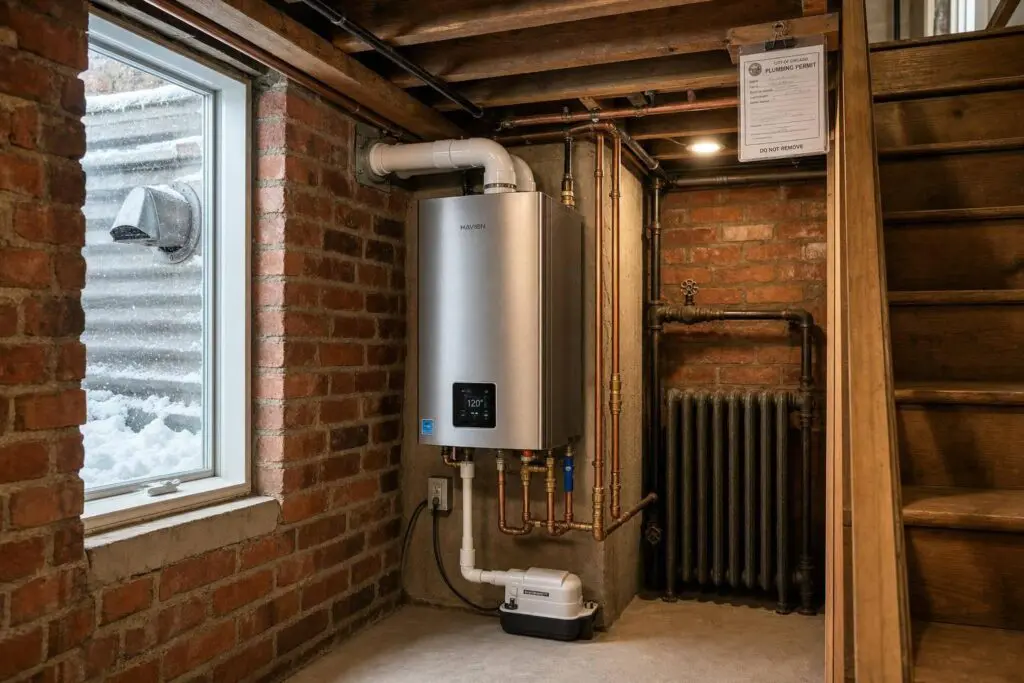
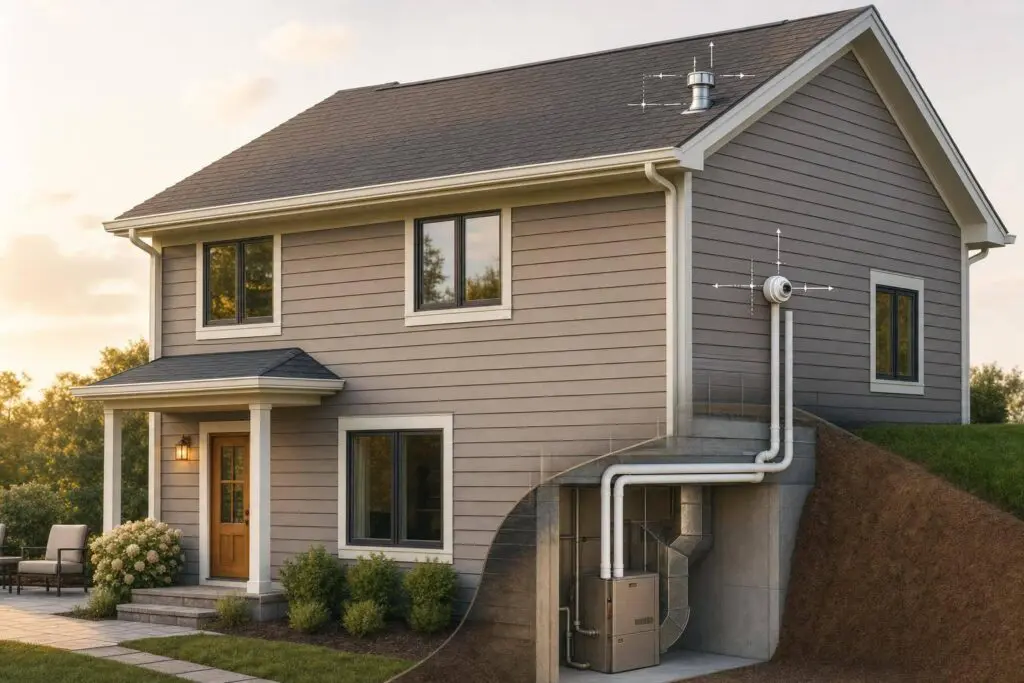
Sidewall venting is common when a roof route just doesn’t make sense. You see this a lot in basement replacement jobs, where two PVC pipes run through the rim joist and foundation wall. From there, the termination setup depends on the furnace vent layout and the clearance limits at the site.
Horizontal Sidewall Terminations for Condensing Furnaces
For condensing furnaces, terminate the vent 12–18 inches above finished grade and above the expected snow level, including drifting snow. In Chicago, the rule is tighter: keep the terminal 10 feet from the lot line and 10 feet above adjacent grade within 10 feet of the terminal. The terminal also needs protection from birds and rodents. Those spacing rules help avoid flue-gas recirculation and reduce nuisance condensate near grade.
Clearance from doors and windows depends on furnace input. For direct-vent condensing furnaces in the 10,000–100,000 Btu/h range, keep the terminal at least 12 inches from any operable door or window. If the furnace is above 100,000 Btu/h, that clearance jumps to 3 feet.
Non-direct-vent power-vent systems need more room. In that case, the vent must be at least:
- 4 feet below any door, operable window, or gravity air inlet
- 4 feet horizontally from those openings
- 1 foot above those openings
Mechanical air-supply inlets, such as HRV, ERV, or makeup air units, also need space. Keep the vent at least 3 feet above any forced-air intake within 10 feet horizontally.
A couple of details are easy to miss. Interior corners formed by two perpendicular walls can hold flue gases and leave stains on siding, so some codes call for the terminal to be at least 3 feet from an interior corner. And when a vent ends near a public sidewalk or driveway, it must be at least 7 feet above the walking surface to cut down the risk of slip hazards from condensate. Category IV furnace wall terminations also must not end directly above public walkways or in spots where condensate vapor could become a nuisance or safety problem.
Sidewall Power Vent and Factory Termination Kits
Use a sidewall power-vent terminal only if the furnace manual lists it for that exact model and firing rate. Manufacturer-listed horizontal and concentric termination kits are built for specific furnace families so they can manage outlet velocity, plume spread, and weather protection.
Before ordering a kit, check that it is listed and approved for the exact furnace model and firing rate being installed. A non-listed termination can put the job out of code and may void the manufacturer warranty.
Installers also need to check whether the furnace pressure switches and condensate management system can handle the added vent resistance from the kit. The manufacturer instructions will spell out the maximum vent length, pipe diameter, pitch, and orientation. If those specs are ignored, the result can be nuisance pressure-switch trips or unsafe operation.
Sidewall Termination Comparison: Standard Hood, Low-Profile Kit, and Concentric Kit
| Factor | Standard Hood (Two-Pipe) | Low-Profile Kit | Concentric Kit |
|---|---|---|---|
| Wall penetrations | Two openings | Varies by kit | One opening |
| Visible profile | Functional; less refined on visible façades | Cleaner look; better for tight urban lots | Most streamlined |
| Service access | Best – each pipe can be inspected independently | Varies by kit | More involved – both flows share one opening |
| Snow/ice risk | Depends on placement | Higher if exposed to deep drifts | Moderate – one blockage affects both flows |
| Clearance planning | Easier to position intake and exhaust separately | Needs careful attention to height above snow level | Both intake and exhaust must satisfy the minimum distances together |
| Retrofit suitability | Flexible in many retrofit layouts | Good where visible hardware needs to be minimized | Useful where wall space is limited |
| Key installer check | Maintain separation between intake and exhaust | Confirm height above snow level | Confirm orientation and elevation per manufacturer specs |
Once the wall termination is set, the next choice is whether the furnace will use two separate pipes or a concentric kit.
Direct-Vent Layouts and Condensing Furnace Routing
Two-Pipe Direct Vent vs. Concentric Termination Layouts
Once you pick the termination type, the next step is deciding how the intake and exhaust get out of the building. Condensing furnaces use separate intake and exhaust paths. From there, the installer has two main options: run them to two terminations or use one concentric kit. Either way, the setup has to stay inside the manufacturer’s venting rules.
A two-pipe direct-vent layout sends the intake and exhaust through separate pipes to separate termination points. That gives you more freedom when routing the lines and usually makes service work easier.
A concentric vent kit puts both air paths through a single wall or roof penetration. The exhaust runs through the inner pipe, while combustion air comes in through the outer pipe.
One detail matters more than it may seem: keep the intake and exhaust in the same outdoor exposure. If they end in different pressure zones, wind can push exhaust back into the intake. That can lead to nuisance shutdowns, freeze-up, or corrosion. Many manufacturer manuals call for tight spacing at the termination to keep both flows in the same pressure zone – often 3 in. on roof terminations and 6 in. on sidewall terminations.
Vent Length, Pitch, and Condensate Management
The layout only works if the vent run stays within the furnace’s length and slope limits. Check the furnace vent table for the right pipe diameter and the maximum equivalent length. And yes, equivalent length includes fittings, so a run that looks short on paper can still go over the limit.
Check the intake and exhaust lengths separately. Also, cut out extra elbows when the layout allows. Every fitting adds resistance.
Horizontal runs should slope about 1/4 in. per foot back toward the furnace so condensate drains to the trap instead of sitting in the pipe. A low spot or reverse pitch – often caused by sagging pipe or weak supports – can hold water. In cold weather, that water can freeze and block airflow. If the pipe passes through an unconditioned space, add insulation to lower the chance of freeze-up.
Layout Comparison: Two-Pipe Direct Vent vs. Concentric Vent Kit
| Factor | Two-Pipe Direct Vent | Concentric Vent Kit |
|---|---|---|
| Wall/roof penetrations | Two separate openings | One combined opening |
| Routing flexibility | Higher – each pipe can be offset independently | Lower – both pipes follow the same path |
| Serviceability | Easier – each pipe inspected independently | More involved – intake and exhaust share one assembly |
| Freeze/recirculation risk | Depends on route length and terminal placement | Co-located flows reduce recirculation risk; shorter exposed section reduces freeze risk |
| Installer priority | Confirm terminal placement and spacing match the model’s pressure-zone requirements | Follow the kit’s Y-fitting, rain cap, support, and sealant instructions |
Next, the contractor checks the site conditions that determine which layout can actually be installed.
On-Site Selection Factors and Conclusion
What a Contractor Reviews Before Choosing a Termination Path
Once roof, sidewall, and direct-vent paths are on the table, the contractor shifts from product options to the building itself. At that point, the job gets very practical. The site often decides the termination path.
Building height and roof design usually come first. If the roof is steep or packed with dormers and valleys, a roof penetration can be harder to install and riskier to service. In that case, a sidewall path or a concentric direct-vent setup is often the simpler choice.
The next filter is available exterior wall space. The contractor needs a clear wall area that keeps the termination away from operable windows, doors, and combustion air inlets. On top of that, the route still has to stay within the unit’s required clearances.
Then comes weather exposure. This matters more than many homeowners expect. A termination on the windward side of the house can leave exhaust moisture freezing on walls and overhangs. Sidewall terminations above decks, patios, or walkways also get a close look, because condensate can drip and turn into ice during sub-freezing weather. In Chicagoland, lake-effect snow patterns and prevailing winter winds can affect both the type of termination and the exact spot where it goes.
The last check is the vent layout itself: total run length, number of fittings, slope, and local code limits. If the vent run is too long, or if it can’t keep a 1/4 in. per foot slope back toward the furnace, the contractor has to choose another route. Local amendments may be stricter than the national code, so the final path also has to match the AHJ’s rules.
Conclusion: Key Points for a Code-Compliant Furnace Vent Termination
The right termination path is the one that satisfies code, the manufacturer’s instructions, and the site’s physical limits at the same time. The manufacturer’s instructions control the install. If those instructions are stricter than the local code minimum, the stricter rule applies. That is why the final choice has to fit the furnace, the building, and the climate all at once.
FAQs
How do I know which vent material my furnace can use?
Check the manufacturer’s installation manual for your furnace model. That’s the first place to look because it tells you which vent materials are approved and what rules apply to that unit.
High-efficiency condensing furnaces usually use plastic venting, such as PVC, CPVC, or polypropylene, as long as the vent stays within the stated temperature limits. Standard-efficiency furnaces often use metal B-vent or a chimney system instead.
This part matters more than it might seem. Using the wrong vent material can lead to carbon monoxide leaks or equipment failure. So before you install anything, confirm the flue gas temperature ratings and check the model-specific vent tables in the manual.
Is roof or sidewall venting better for my home?
It depends on your home’s layout, your furnace model, and local code rules.
Sidewall venting is common with high-efficiency condensing furnaces that use PVC piping. But placement matters. The vent usually needs to sit at least 12 inches above expected snow levels and stay clear of windows, doors, and walkways.
Roof venting can make more sense when sidewall space is tight or when you want to cut the risk of snow blocking the vent. In either case, a professional technician should confirm the safest option and make sure the installation meets code.
When should a concentric vent kit be used?
Use a concentric vent kit when you want one opening through the wall or roof instead of two. That can be a big help when looks matter or when framing makes extra openings a pain.
These kits are approved only for Category IV condensing, direct-vent furnaces. Since they add resistance to the vent system, they can cut down the allowed vent length. So before you install one, check the furnace manual for the right pipe size, material, and slope.